Table of Contents
Advertisement
Quick Links
STEERING SYSTEMS
PRO TRIM
INSTALLER: THESE INSTRUCTIONS CONTAIN IMPORTANT SAFETY INFORMATION
AND MUST BE FORWARDED TO BOAT OWNER.
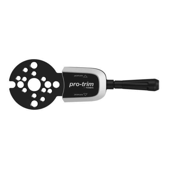
PT1000-2 and PT2000-2
PRO TRIM™ Single/Dual Bezel
EN
Switch Assembly
Installation Manual . . . . . . . . . . . . . . . . . . . . .2
WARNING
Cancer and Reproductive Harm
www.P65Warnings.ca.gov
Revision 0 Form No. IS-PT1000/2000-2 04/21 | ©2021 Dometic Corporation
Advertisement
Table of Contents

Subscribe to Our Youtube Channel
Related Manuals for Dometic PRO TRIM PT1000-2

Summary of Contents for Dometic PRO TRIM PT1000-2
- Page 1 Switch Assembly Installation Manual .....2 WARNING Cancer and Reproductive Harm www.P65Warnings.ca.gov Revision 0 Form No. IS-PT1000/2000-2 04/21 | ©2021 Dometic Corporation...
-
Page 2: Table Of Contents
For up-to- date product information, please visit www.dometic.com. 1 .1 Recognize Safety Information Contents This is the safety alert symbol . It is used to alert Explanation of Symbols and Safety you to potential physical injury hazards. -
Page 3: Supplemental Directives
The manufacturer accepts no liability for damage in the SeaStar Pro™ Hydraulic Helms (Tilt and Non-tilt) following cases: If your steering system is not listed, please call Dometic Technical Support • Faulty assembly or connection • Damage to the product resulting from mechanical influences and excess voltage... -
Page 4: Components List
Wiring Diagram PRO TRIM™ Single/Dual Bezel Switch Assembly 3 .2 Components List Recommended Tools Phillips Screwdriver Electrical Tape The images used in this document are for reference purposes only. Crimping Tool 3/16 in. Drill Bit (Optional) Socket Wrench Drill (Optional) Wrench Needle Nose Pliers (Optional) -
Page 5: Mounting On An Xtreme Or No Feedback (Nfb) Rotary Steering System (Non-Tilt)
PRO TRIM™ Single/Dual Bezel Switch Assembly Installation 5 .1 Mounting on an Xtreme or No If your bezel already has recessed holes at these locations, then no drilling of the bezel is necessary. Feedback (NFB) Rotary Steering System (Non-Tilt) 3 Xtreme and NFB Rotary Steering System Bezels 5 Rotary Steering System Wire Passage—Options 1 and 2 Holes NFB and NFB Bezel... -
Page 6: Mounting On A Rack Steering System
Installation PRO TRIM™ Single/Dual Bezel Switch Assembly 8. Depending on the option chosen in step 4, feed the wires: – Through the bezel and dash. – Through the dash. – Underneath the dash. 9. Place the bezel with attached switch assembly over the steering wheel shaft (see Figure 7) and tighten the bezel attachment screws. - Page 7 PRO TRIM™ Single/Dual Bezel Switch Assembly Installation 5. Attach the wires to the switch; red wire to the center terminal, green wire to the top terminal, and blue wire to the bottom terminal (see Figure 2). 9 Rack Steering System Drill Locations Rack Steering System Drill Locations 2.
-
Page 8: Mounting On A Performance Tilt Steering
Installation PRO TRIM™ Single/Dual Bezel Switch Assembly 8. Place the bezel with attached switch assembly over 3. Place the switch assembly bracket against the boot, the steering wheel shaft (see Figure 12) and tighten lining up the center holes. Punch mark the holes the bezel screws. - Page 9 PRO TRIM™ Single/Dual Bezel Switch Assembly Installation If installing a single switch, be sure the hole is drilled on the side the switch lever will be installed. 7. Attach the wires to the switch; red wire to the center terminal, green wire to the top terminal, and blue wire to the bottom terminal (see Figure 2).
-
Page 10: Mounting On A Seastar Or Seastar Pro Hydraulic Steering System
Installation PRO TRIM™ Single/Dual Bezel Switch Assembly 20. After fully tightening the screws, follow the instruction manual for your tilt mechanism to learn how to attach the boot to the bezel. 21. Work the lip on the rubber boot into the accessory channel on the bezel. -
Page 11: Wiring The Connections To The Marine
PRO TRIM™ Single/Dual Bezel Switch Assembly Installation 5. Place the switch assembly over the steering wheel – Wiring for horn connection: shaft. Horn wires are typically found under the dash. It may be necessary to use a jumper wire on 6. -
Page 12: Testing The Installation
Check the wire connections at the wire harness. Place the packaging material in the appropriate recycling waste bins, whenever possible. Consult Go to www.dometic.com to find technical support a local recycling center or specialist dealer for in your area. -
Page 13: Warranty Information
WWW.SEASTARSOLUTIONS.COM/SUPPORT-2/ WARRANTY-2/SEASTAR-SOLUTIONS-WARRANTY. IF YOU HAVE QUESTIONS, OR TO OBTAIN A COPY OF THE LIMITED WARRANTY FREE OF CHARGE, CONTACT: DOMETIC CORPORATION : SEASTAR SOLUTIONS 640 NORTH LEWIS ROAD LIMERICK, PENNSYLVANIA 19468 1-610-495-7011 EXT 2 ts.mechanical@dometic.com INSTALLER: THESE INSTRUCTIONS CONTAIN IMPORTANT SAFETY INFORMATION... - Page 14 PRO TRIM™ Single/Dual Bezel Switch Assembly...
- Page 15 PRO TRIM™ Single/Dual Bezel Switch Assembly...
- Page 16 Mobile living made easy. dometic .com CONTACT US dometic .com/en-us/terms-and-conditions-consumer/contact-us A complete list of Dometic companies, which comprise the Dometic Group, can be found in the public filings of: DOMETIC GROUP AB Hemvärnsgatan 15 SE-17154 Solna Sweden...
Need help?
Do you have a question about the PRO TRIM PT1000-2 and is the answer not in the manual?
Questions and answers