Advertisement
Table of Contents
1
Koolance TMS-100K Installation Guide
Hardware Installation
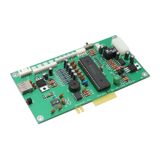
The TMS interface card can be installed into a PCI or PCI-Express slot (with included L-bracket), 3.5" bay (with included tray),
or optionally adapted to a 5.25" bay. It utilizes one external or internal USB port, and is powered by a direct 12V power supply
connection.
First, connect all necessary wires to the TMS card EXCEPT THE USB CABLE. The internal or external USB cable will be
connected after software installation. If necessary, wire extensions for fans and the pump are included with the TMS-100K.
Decide whether the TMS card will use the L-bracket (motherboard slot installation) or 3.5" tray (drive bay installation) and mount
the appropriate piece with the included screws. The cables will be more diffi cult to attach if not done before screwing the TMS
card into the 3.5" tray.
12V 4-pin Molex
power supply
connection
ATX pass-through wire: enables the hardware safety shutdown
feature.
computer chassis main power switch.
Connect the male ATX power lead from theTMS board to the
Connect the other female ATX power lead to
the motherboard's power switch connection
(often marked "PWRSW", "PWSW", or
"PWBT").
This is the connection that would normally
receive the chassis power switch lead
directly.
v1.00
Connection
Indicator LED
External USB Connection
Coolant fl ow meter
(sold separately)
Coolant fl ow meter LED switch: off, on,
pulse (according to fl ow rate)
Pump power connection:
CAUTION:
Only Koolance PMP-400 model pumps are compatible with
!
this connection. The PMP-400 is found in Koolance PC4-1000 rev.2,
RP-1000 rev.2, and TNK-400 series products. Other models (such as
the PC2, PC3, Exos, etc.) may damage the TMS board or computer
power supply if connected.
Internal USB Connection
Fan power connections:
J4 - Primary tachometer fan
J5, J6, J13 - Extra (optional) fans
Temperature sensor connections:
J8 - represented in software as "CH1"
J9 - represented in software as "CH2"
J10 - represented in software as "CH3"
J11 - represented in software as "CH4"
J12 - represented in software as "CH5"
Advertisement
Table of Contents

Related Manuals for Koolance TMS-100K

Summary of Contents for Koolance TMS-100K
- Page 1 First, connect all necessary wires to the TMS card EXCEPT THE USB CABLE. The internal or external USB cable will be connected after software installation. If necessary, wire extensions for fans and the pump are included with the TMS-100K. Decide whether the TMS card will use the L-bracket (motherboard slot installation) or 3.5” tray (drive bay installation) and mount the appropriate piece with the included screws.
- Page 2 Koolance TMS-100K Installation Guide v1.00 Software Installation After connecting the TMS board (except the USB cable) and mounting the card within the computer case, insert the CD-ROM to launch the installation program. Select the features you would like to install. The PL-2303 Drivers will be necessary for the TMS software to communicate with the hardware card.
Need help?
Do you have a question about the TMS-100K and is the answer not in the manual?
Questions and answers