
Related Manuals for EWM PHW 100

Summary of Contents for EWM PHW 100
- Page 1 Operating instructions welding torch PHW 100 099-008232-EW501 Observe additional system documents! 26.05.2020...
- Page 2 +49 2680 181-0. A list of authorised sales partners can be found at www.ewm-group.com/en/specialist-dealers. Liability relating to the operation of this equipment is restricted solely to the function of the equipment. No other form of liability, regardless of type, shall be accepted.
-
Page 3: Table Of Contents
Declaration of Conformity ....................7 3.2.3 Service documents (spare parts) ................... 7 4 Machine description – quick overview ....................8 PHW 100 ............................8 5 Design and function ..........................9 Scope of delivery ........................... 9 Transport and installation ......................10 5.2.1... - Page 4 Disposing of equipment ........................ 29 7 Rectifying faults............................ 30 Checklist for rectifying faults ......................30 Vent coolant circuit ........................31 8 Technical data............................32 PHW 100 ............................32 8.1.1 Dimensions ........................32 9 Accessories ............................33 General............................33 Welding torch cooling system ...................... 33 10 Replaceable parts ..........................
-
Page 5: For Your Safety
For your safety Notes on using these operating instructions For your safety Notes on using these operating instructions DANGER Working or operating procedures which must be closely observed to prevent imminent serious and even fatal injuries. • Safety notes include the "DANGER" keyword in the heading with a general warning symbol. •... -
Page 6: Part Of The Complete Documentation
For your safety Part of the complete documentation Symbol Description Symbol Description Output Signal light lights up in red Time representation (e.g.: wait 4 s / Signal light flashes red actuate) Interruption in the menu display (other setting options possible) Tool not required/do not use Tool required/use Part of the complete documentation... -
Page 7: Intended Use
3.2.1 Warranty For more information refer to the "Warranty registration" brochure supplied and our information regarding warranty, maintenance and testing at www.ewm-group.com! 3.2.2 Declaration of Conformity This product corresponds in its design and construction to the EU directives listed in the decla- ration. -
Page 8: Machine Description - Quick Overview
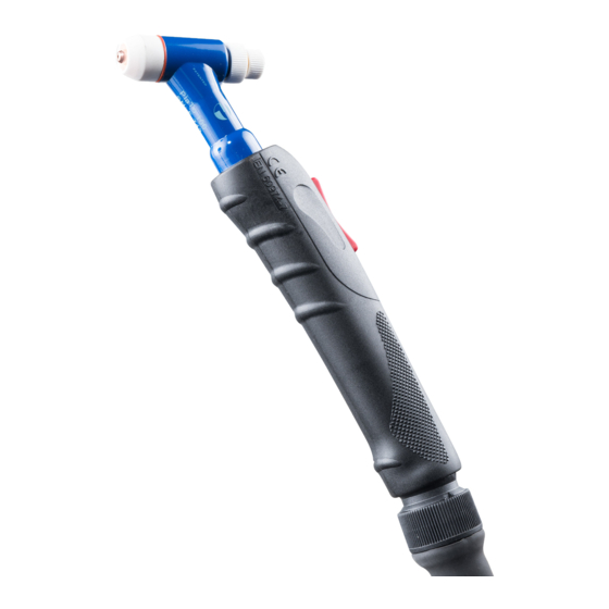
Machine description – quick overview PHW 100 Machine description – quick overview PHW 100 Figure 4-1 Item Symbol Description Grip plate Torch trigger Back cap Collet housing Torch body Gas nozzle Plasma nozzle 099-008232-EW501 26.05.2020... -
Page 9: Design And Function
Design and function Scope of delivery Design and function WARNING Risk of injury from electrical voltage! Contact with live parts, e.g. power connections, can be fatal! • Observe the safety information on the first pages of the operating instructions! • Commissioning must be carried out by persons who are specifically trained in handling power sources! •... -
Page 10: Transport And Installation
Design and function Transport and installation Transport and installation CAUTION Risk of accidents due to supply lines! During transport, attached supply lines (mains leads, control cables, etc.) can cause risks, e.g. by causing connected machines to tip over and injure persons! •... -
Page 11: Welding Torch Cooling System
Design and function Welding torch cooling system Figure 5-1 Item Symbol Description Electrode High voltage Plasma gas Gas nozzle Work piece Plasma nozzle Shielding gas Welding torch cooling system Coolant mixtures! Mixtures with other liquids or the use of unsuitable coolants result in material damage and ren- ders the manufacturer's warranty void! •... -
Page 12: Permitted Torch Coolant
Design and function Welding torch cooling system 5.4.1 Permitted torch coolant Coolant Temperature range KF 23E -10 °C to +40 °C Figure 5-2 Item Symbol Description Water cooling Shielding gas Shielding gas exit Part of the heat is released to the cooling system of the welding torch over the plasma nozzle and gas lens, and part of the shielding gas is blown out of the welding torch. -
Page 13: Welding Torch Connection
Design and function Welding torch connection Welding torch connection Depending on the machine, various adapter sets are required to connect the welding torch. 5.5.1 Connection variant Microplasma 25, -55, -105 Figure 5-4 Item Symbol Description Quick connect nipple (9 mm / 0.35 inch) Coolant feed (blue) Quick connect nipple (9 mm / 0.35 inch) Coolant return (red) -
Page 14: Connection Variant Microplasma 20, -50
Design and function Ultraviolet radiation 5.5.2 Connection variant Microplasma 20, -50 Figure 5-5 Item Symbol Description Connecting nipple (M12x1) Coolant feed (blue) Connecting nipple (M12x1) Coolant return (red) Connecting nipple (G 1/4” LH) Shielding gas (yellow) Connecting nipple (G 1/4" RH) Plasma gas (red) Connector plug (9 mm / 0.35 inch) Welding current connection... -
Page 15: Gas Supply (Shielding And Plasma Gas)
Design and function Gas supply (shielding and plasma gas) Welding current Eye protection filter < 1 A Level 5 1 to 2.5 A Level 6 2.5 to 5 A Level 7 5 to 10 A Level 8 10 to 15 A Level 9 >... -
Page 16: Shielding Gas
Design and function Tables of current carrying capacity • Place the shielding gas cylinder into the relevant cylinder bracket. • Secure the shielding gas cylinder against falling over. Use only 2-stage bottle pressure regulators with bar display on the output side. Argon is usually used as the arc-forming gas. -
Page 17: Tables Of Current Carrying Capacity
Current carrying capacity and plasma gas quantities for standard nozzle 18 mm / 0.71 inch Guide values for the current-carrying capacity of PHW 100 plasma nozzles, electrode at the negative po- le, electrode diameter 1.0, 1.5, 2.4 mm / 0.04, 0.06, 0.09 inch. -
Page 18: Current Carrying Capacity And Plasma Gas Quantities For Standard Nozzle 23 Mm / 0.91 Inch
Design and function Tables of current carrying capacity 5.8.2 Current carrying capacity and plasma gas quantities for standard nozzle 23 mm / 0.91 inch Diameter of plasma nozzles Amount of plasma Electrode diameter Current 0.5 mm / 0.02 inch 1.5 mm / 0.06 inch 0.1-0.2 l/min 0.03-0.05 gal/min 0.6 mm / 0.02 inch... -
Page 19: Current Carrying Capacity And Plasma Gas Quantities For The Electrode At The Positive Pole Or Ac Operation
Current carrying capacity and plasma gas quantities for the electrode at the posi- tive pole or AC operation Guide values for current carrying capacity of PHW 100 plasma nozzles, electrode > see 5.9.3 chapterof dimension “L” at the positive pole or in AC operation, electrode diameter 3.2 mm / 0.13 inch. -
Page 20: Changing The Contact Tip
Design and function Wear part replacement 5.9.2 Changing the contact tip The choice of the plasma nozzle depends on the application and the associated current load > see 5.8 chapter. The plasma nozzle should be replaced when the nozzle channel is damaged and therefore no longer cir- cular. -
Page 21: Regrinding The Electrode
Design and function Wear part replacement Figure 5-11 5.9.3.1 Regrinding the electrode The electrode shape is decisive for a good welding result. Therefore, it is necessary to grind electrodes by machine to the correct shape before use. The electrode must be replaced if the electrode tip is exces- sively worn, tarnished too much, or burned back asymmetrically. -
Page 22: Removal And Reassembly Of The Electrode With Mounted Electrode Clamping Unit
Design and function Wear part replacement Regrinding electrodes centrically Figure 5-13 The tip of the electrode should be centred in the longitudinal axis of the electrode. In the case of devia- tions, there is a risk that the arc will become unstable. Especially in automated welding, a non-centred electrode tip leads to ignition next to the proper ignition point. -
Page 23: Setting The Electrode Gap
Design and function Wear part replacement • Remove the electrode (1) by holding the knurled ring of the collet housing (3) with one hand and turn- ing the knurled back cap (4) anti-clockwise approx. 2 turns with the other hand. •... -
Page 24: Guide Values For Basic Setting (Electrode At The Negative Pole)
Design and function Wear part replacement 5.9.3.5 Guide values for basic setting (electrode at the negative pole) Dimension “L” for nozzle diameter Nozzle type Nozzle diameter Standard Long Overlong Extra-long Angled Angled nozzle nozzle Standard Long 0.5 mm / 0.02 inch 17.0 mm / 21.5 mm / 24.5 mm /... -
Page 25: Installation Of The Electrode With The Electrode Clamping Unit Removed
Design and function Wear part replacement 5.9.3.7 Installation of the electrode with the electrode clamping unit removed Figure 5-18 Item Symbol Description Electrode Sealing ring of the gas nozzle Torch body Collet chuck Sealing ring of the collet housing 099-008232-EW501 26.05.2020... -
Page 26: Commissioning
Design and function Commissioning Item Symbol Description Collet housing Sealing ring of the back cap Back cap Calliper with round depth measuring rod Electrode setting gauge • Remove all sealing rings from the torch body (3) and rub sparingly with lubricant VR 500 . -
Page 27: 5.10.2 Double Arc
Design and function Commissioning 5.10.2 Double arc When the current load is too high or the torch held at too steep an angle, a second arc will form between workpiece and plasma nozzle. Figure 5-20 Increased current load and a torch position that is too skew lead to considerable plasma nozzle wear. -
Page 28: Maintenance, Care And Disposal
Maintenance, care and disposal General Maintenance, care and disposal General DANGER Risk of injury due to electrical voltage after switching off! Working on an open machine can lead to fatal injuries! Capacitors are loaded with electrical voltage during operation. Voltage remains present for up to four minutes after the mains plug is removed. -
Page 29: Monthly Maintenance Tasks
• Information about returning used equipment or about collections can be obtained from the respective municipal administration office. • In addition to this, returns are also possible throughout Europe via EWM sales partners. 099-008232-EW501 26.05.2020... -
Page 30: Rectifying Faults
Rectifying faults Checklist for rectifying faults Rectifying faults All products are subject to rigorous production checks and final checks. If, despite this, something fails to work at any time, please check the product using the following flowchart. If none of the fault rectification procedures described leads to the correct functioning of the product, please inform your authorised dea- ler. -
Page 31: Vent Coolant Circuit
Rectifying faults Vent coolant circuit Pore formation Inadequate or missing gas shielding Check shielding gas setting and replace shielding gas cylinder if necessary Shield welding site with protective screens (draughts affect the welding result) Unsuitable or worn welding torch equipment Check size of gas nozzle and replace if necessary ... -
Page 32: Technical Data
Technical data PHW 100 Technical data PHW 100 max. Power range 100 % Duty cyc- 0,5-100 A Direct voltage (Welding torch polarity "-", Electrode Ø: le DC at 40° C 1,5/2,4 mm / 0,06/0,09 inch) max. 35 A Direct voltage (Welding torch polarity "+", Electrode Ø: 3,2 mm / 0,13 inch) max. -
Page 33: Accessories
Accessories General Accessories Performance-dependent accessories like torches, workpiece leads, electrode holders or intermediate hose packages are available from your authorised dealer. General Type Designation Item no. ELECTRODE ADJUSTMENT Electrode setting gauge 094-008262-00000 GAUGE ON Adap Microplasma new Adapter for connecting a welding torch with screw 092-003539-00000 coupling to Microplasma 25/55/105 Welding torch cooling system... -
Page 34: Replaceable Parts
Replaceable parts PWH/PWM 100 Replaceable parts The manufacturer's warranty becomes void if non-genuine parts are used! • Only use system components and options (power sources, welding torches, electrode hold- ers, remote controls, spare parts and replacement parts, etc.) from our range of products! •... - Page 35 Replaceable parts PWH/PWM 100 Item Order number Type Name 094-008550-00000 PNOZZ LONG 2.2 mm Plasma nozzle, long 094-008259-00000 PNOZZ LONG 2.4 mm Plasma nozzle, long 094-008551-00000 PNOZZ LONG 2.6mm Plasma nozzle, long 094-008260-00000 PNOZZ LONG 3.0mm Plasma nozzle, long 094-008479-00000 PNOZZ LONG 3.2 mm Plasma nozzle, long 094-019628-00000 TUBE Ø...
-
Page 36: Appendix
Appendix Searching for a dealer Appendix 11.1 Searching for a dealer Sales & service partners www.ewm-group.com/en/specialist-dealers "More than 400 EWM sales partners worldwide" 099-008232-EW501 26.05.2020...
Need help?
Do you have a question about the PHW 100 and is the answer not in the manual?
Questions and answers