Table of Contents

Subscribe to Our Youtube Channel
Related Manuals for GMW TG Basic 2

Summary of Contents for GMW TG Basic 2
- Page 1 TG Basic 2 / TG Basic 2+ Appliance Tester DIN VDE 0701/0702 ÖVE 8701 - 1 - 2 Gilgen, Müller & Weigert (GMW) GmbH & Co. KG Am Farrnbach 4A Tel: +49 (0) 9103 7129-0 90556 Cadolzburg Fax: +49 (0) 9103 7129-205/207...
-
Page 2: Product Overview
Product overview APPLIANCE TESTER LOW VOLTAGE AND MEDIUM VOLTAGE CURRENT CONVERTER ENERGY MANAGEMENT ANALOGUE DISPLAY UNITS DIGITAL PANEL-MOUNTED MEASURING INSTRUMENTS MEASURING TRANSDUCERS PRINTERS S H U N T S SWITCH CABINET COMPONENTS P O T E N T IO M E T E R S LOW VOLTAGE SWITCHGEARS www.g-mw.de... - Page 3 All texts, illustrations and technical specifications were compiled with care. In spite of this care, errors cannot be ruled out entirely. The author and the manufacturer of the test device cannot assume legal responsibility nor any liability for incorrect information and the consequences thereof.
- Page 4 3 Scope of delivery 4 Connections, operating and display elements 4.1 Mains connection, Neutrik powerCON blue 4.2 Connection, TG Basic 2 + non-heating appliance plug 4.3 Connection, TG basic 2 4.4 Connection, shockproof test socket 4.5 Red measuring socket „Probe“...
- Page 5 9.12 Substitute leakage current measurement probe-probe 9.13 Voltage measurement 9.14 Differential current measurement on test objects with shockproof plugs 9.15 Clip-on ammeter function test (TG Basic 2+ only) 9.16 RCD function test (TG Basic 2+ only) 9.17 Wiring test (in the Test-Master app only) 10 Error message, troubleshooting 10.1 The display is off...
- Page 6 General safety and warning notices The „TG Basic 2 (+)“ test device was built and tested to the following safety regulations: • DIN EN 61010-1 (VDE 0411 Part 1), • DIN EN 61010-2-30; VDE 0411-2-030 „Safety requirements for electrical equipment for measurement, control, and laboratory use, General requirements“...
- Page 7 Repair work and modifications to the test device must only be carried out by the manufacturer itself or specialists authorised by the manufacturer! Only specialists may perform repair work on mains adapter cables. Only the original replacement parts specified by the manufacturer may be fitted and used! If safe operation is no longer possible, e.g.
- Page 8 Meaning of symbols on the device Warning hazardous situation WARNING! HEED documentation The device must not be disposed of with domestic waste. European conformity marking 300 V CAT II Maximum permissible voltage and measurement category between the connections and the earth Meaning of symbols in the operating manual WARNING! Warning: Voltage!
-
Page 9: Scope Of Delivery
The TG basic 2 / TG basic 2+ test device is a measuring device for evaluating the effectiveness of protective measures on electrical appliances in accordance with DIN VDE 0701-0702 respektive ÖVE 8701-1-2 Scope of delivery • 1 TG basic 2 or TG basic 2+ test device •... -
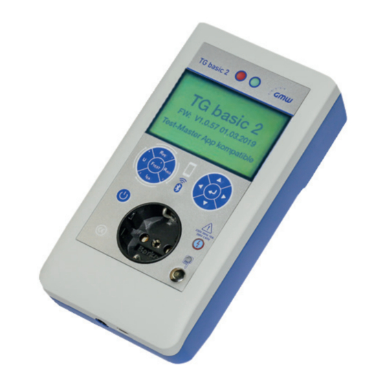
Page 10: Connections, Operating And Display Elements
Connections, operating and display elements Bild 2 www.g-mw.de... - Page 11 Mains connection Neutrik Power CON blue Non-heating appliance plug connection for extension cables and RCD testing (TG Basic 2+), IEC 60320 C19 Connection for red measuring line „Probe“ or for connecting adapter A1 and A2 (Rpe measurement) (for TG Basic 2 only) Connection for black measuring line „GND“...
- Page 12 Red measuring socket „Probe“ (3) Connecting the measuring line for the plus pole for measurement of the protective earth conductor resistance, insulation resistance. Measurement input for voltage, substitute leakage current and touch current measurement. Black measuring socket „GND“ (4) Connecting the measuring line for the minus pole for measurement of the protective earth conductor resistance, touch current, voltage and insulation resistance.
-
Page 13: Functionality Description
The measurement electronics are supplied via an internal fuse. Memory The measurement values can only be stored in the Test-Master app on a mobile phone or tablet. Test devices TG Basic 2 / TG Basic 2+ do not have internal memory. www.g-mw.de... - Page 14 Testing the electrical connection The operator is responsible for the safety of the electrical installation (incl. on-site electrical connection and equipotential bonding system), in accordance with the fundamental statutory regulations (accident prevention regulations, valid standards). Testing the electrical connection is not part of the test requirements for modification, testing and repeat testing on the electrical devices.
- Page 15 The test device is supplied via the mains connection on the top of the device. The TG Basic 2 and TG Basic 2+ devices are automatically deactivated completely after approx. 10 min. Important note! For the TG Basic 2+ tester: The rechargeable batteries are fully charged after approx.
- Page 16 • The „Discharge battery“ function can be found on the Connection menu of the TG Basic 2+. • Press the button to start the discharge process; the screen switches off, the relays switch on and the red LED flashes.
- Page 17 Testing electrical appliances The tests required by standards are implemented in the integrated test sequences. Before performing the test, the test object has to be classified in the Profile menu. After repairs, modifications and repeat testing, electrical appliances must also offer users protection comparable with the protection of new appliances against electrical hazards.
- Page 18 Electrical connection According to the fundamental statutory regulations, the accident prevention regulations and valid standards, it is not the manufacturer of the appliances to be connected who is responsible for the safety of the on-site electrical connection and, where applicable, connection of the equipotential bonding system to the device;...
- Page 19 The arrow keys can be used to activate additional functions, like standby power measurement and polarity reversal of phase and neutral conductor. • Additional functions in the TG Basic 2+ • Clip-on ammeter function test = Differential current and phase current can be tested here with a clip-on ammeter.
- Page 20 Function test After completion of the electrical test, a function test must be carried out on the appliance. A partial test can be sufficient in accordance with legal requirements. Inspecting the inscriptions Safety-related inscriptions, for example stipulations on the direction of rotation, must be checked and, where necessary, renewed or supplemented in suitable form.
- Page 21 ‘Enter’ to finish. The measured value is saved until the next restart. The TG Basic 2+ testers do not always need to be supplied with mains voltage. Certain tests can be carried out with battery power.
- Page 22 Protective earth conductor measurements of alternating current test objects PE conductor measurement: Sample the housing parts with the PE conductor probe and move the connection cable. Select „Plug“ under RPE measurement for individual measurements on the appliance. www.g-mw.de...
- Page 23 Set the automatic test sequence „Extension (protection class I)“ in the Test-Master app. Sample all PE conductor contacts. For individual measurements on the appliance, select „Plug“ under RPE measurement and contact the PE conductor with adapter [A1] or [A2] (TG Basic 2). Use the included test cable for measurement with the TG basic 2+. www.g-mw.de...
- Page 24 Fig: TG Basic 2+ Fig: TG Basic 2 www.g-mw.de...
- Page 25 Protective earth conductor resistance measurement(e.g. three-phase current test objects) with two measuring lines Select „Probe - Probe“ under RPE measurement for individual measurements on the appliance. Insert the measuring line in the black socket of the test device and connect it to the PE conductor connection of the test object.
- Page 26 Touchable, insulated, conductive parts Select „Probe - Probe“ under RPE measurement for individual measurements on the appliance. Measuring touchable parts that are not connected to PE: Sample these parts with the probe. For moving parts, such as those in a drill, sample the chuck in the rotating operating condition, ideally with the optional brush probe.
- Page 27 Insulation resistance LN-PE Automatic test sequence in the Test-Master app: Protection class I (with PE) „Active“ or individual test „Insulation resistance LN-PE“. For individual measurements on the appliance, select „LN - PE“ under = RISO measurement. Check the preset parameters (heat el. YES/NO), correct test voltage (250 V/500 V) if necessary. Insert the test object in the test socket.
- Page 28 Insulation resistance LN-PE of three-phase current test objects with the extension cable adapter Automatic test sequence „Protection class I (with PE) active“ in the Test-Master app or individual test. „Insulation resistance LN-PE’“ For individual measurements on the appliance, select „LN - PE“ under = insulation test.
- Page 29 9.10 Substitute leakage current measurement LN-PE The „Substitute leakage current measurement“ is not available in the app!!! Note! The substitute leakage current measurement may only be carried out after the insulation resistance test has been passed. Note! The substitute leakage current measurement is not a sufficient test if the appliance has switching elements that switch all poles, as this measurement does not test the underlying current circuits.
- Page 30 9.11 Substitute leakage current measurement LN probe The measurement is made when no voltage is present in the test object. This measurement is carried out between LN and touchable parts insulated from PE (including SELV parts – e.g. the secondary side of power adaptors). 9.12 Substitute leakage current measurement probe-probe Connect the measuring device as shown in the diagram.
- Page 31 9.13 Voltage measurement Insert the test object in the test socket. Automatic test sequence in the Test-Master app: „Protection class I (with PE) active“ or individual measurement. For individual measurements on the appliance, under = Voltage measurement. The Voltage measurement. Caution: The mains voltage is switched on at the shockproof test socket! As soon as there is mains voltage at the test socket, the LED on the high voltage display lights up in red.
- Page 32 9.14 Differential current measurement on test objects with a shockproof plug Differential current measurement, function test: Insert the test object in the test socket. Automatic test sequence in the Test-Master app1 and „Protection class I (with PE) active“ or individual test „Diff.+touch current+function test“.
- Page 33 9.15 Clip-on ammeter function test (TG Basic 2+ only) Connect the TGSZ 40 clip-on ammeter to test device TG Basic 2+ at the clip-on ammeter connection (15). This cannot be implemented via an automatic sequence in the app!!! For individual measurements on the appliance, select „Clip-on ammeter function test“ under .
-
Page 34: Error Message, Troubleshooting
Error message, troubleshooting 10.1 The display is off Note: The L or N conductor connection is probably not OK. If the mains is OK, the internal fuse may have blown. 10.2 Touch current measurement shows 0.000 mA That is not an error, it is the normal status. 10.3 Touch current measurement over 0.5 mA Attention! There is voltage present at the touchable conductive parts!!! -
Page 35: Technical Data
Technical data Alternating current 230 V ± 10% Mains power supply Test object connection: 16 A shockproof Operating ambient temperature: 0 – 40°C Measurements Operating error 5% of the measured value + 1% of the range Measuring range: 0,000 Ω ...4,000 Ω. Protective earth conductor resistance Idle voltage 10 V (probe-PE, probe-PE-mains, probe-probe):... -
Page 36: Service Information
Dimensions 210 x 110 x 80 mm TG basic 2 (incl. soft pouch and accessories) Weight TG basic 2+ (incl. soft pouch, accessories and batteries) Disposal The end user disposes of the device appropriately in accordance with the valid directives. -
Page 37: Warranty And Guarantee
Warranty and guarantee Test devices TG Basic 2 and TG Basic 2+ are subject to strict quality control. Every test device comes with a corresponding test protocol with all calibration data. Unless otherwise agreed, the test device is guaranteed for 12 months after the device is handed over. Our General Terms and Conditions also apply. - Page 38 Mains connection cable, GER On request Neutrik powerCon blue, 1.5 m, CH plug Non-heating appliance connection line, 0.6 m On request (For extension and RCD test, TG Basic 2+ only) Three-phase adapter VLCEE 16 A 7920019030 Three-phase adapter VLCEE 32 A 7920019040...
- Page 39 Differential clip-on ammeter TGSZ 40 79200190010 Adapter for a standard differential clip-on ammeter TGSZ 40 On request Adapter for testing extension cables 7920018680 (for TG Basic 2 only) Adapter for testing non-heating appliance cables (for TG Basic 2 only) Software Omni-Remote (database software) 7920019130 8“...
- Page 40 Gilgen, Müller & Weigert (GMW) GmbH & Co. KG Gilgen, Müller & Weigert (GMW) GmbH & Co. KG Am Farrnbach 4A...
Need help?
Do you have a question about the TG Basic 2 and is the answer not in the manual?
Questions and answers