Table of Contents
Advertisement
Quick Links
Advertisement
Table of Contents

Related Manuals for NovaStar J6


Summary of Contents for NovaStar J6
- Page 1 Seamless Switcher V3.0.0 User Manual...
-
Page 2: Table Of Contents
J6 Seamless Switcher User Manual Contents 1 Overview ..................................1 1.1 Introduction ................................1 1.2 Features ..................................1 2 Appearance ..................................3 2.1 Front Panel ................................3 2.2 Rear Panel ................................. 4 2.3 Dimensions ................................6 3 Applications ..................................7 4 Menu Operations ................................ -
Page 3: Overview
4 DVI output connectors can be used together for output, which can realize an up to 8KK loading capacity of each J6 unit. When it is in Switcher mode, a maximum of 2 DVI output connectors can be used together for output, which can realize an up to 4KK loading capacity of each J6 unit. - Page 4 The device can be controlled via its front panel, the smart control software V-Can or C1 event controller. Multiple J6 units controlled by one C1 unit You can perform operations, such as FTB, freeze or Take operation, to multiple J6 units on the C1. AUX In Switcher mode, the device supports the AUX function.
-
Page 5: Appearance
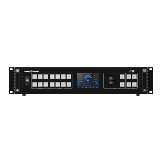
J6 Seamless Switcher User Manual 2 Appearance 2.1 Front Panel Button Description ON/OFF Press ON to power on the device. button Press OFF to power off the device. Layer Open or close a layer, and show the layer status. -
Page 6: Rear Panel
2.2 Rear Panel Notes: The J6 provides two default configurations that differ in Input-F and Input-G connectors on the rear panel. DP 1.1 and HDMI 1.4 connectors support at most 2 layers. Other connectors support at most 6 layers. - Page 7 Each group includes a main connector and a backup connector. The J6 supports dual-link DVI output mode. When the output is set to dual- link mode, DVI 1 and DVI 3 are used as output connectors, while DVI 2 and DVI 4 are unavailable.
-
Page 8: Dimensions
J6 Seamless Switcher User Manual 2.3 Dimensions Unit: mm www.novastar.tech... -
Page 9: Applications
J6 Seamless Switcher User Manual 3 Applications The J6 supports dual system modes: Splicer and Switcher. The connections for two modes are shown in Figure 3-1 Figure 3-2. Figure 3-1 Connections for Splicer mode Figure 3-2 Connections for Switcher mode Note: This product can only be worked horizontally. -
Page 10: Menu Operations
J6 Seamless Switcher User Manual 4 Menu Operations 4.1 Operation Instructions Knob On the home screen, pressing the knob enters the operation menu screen. On the operation menu screen, rotating the knob selects a menu item, and pressing the knob confirms the selection or enters the submenu. - Page 11 J6 Seamless Switcher User Manual Area Description currently used source signal is displayed. Screen layout Display the current screen layout and resolution. screen In Spicer mode, the supported screen layouts are 1×1, 1×2, 2×1, 1×3, 3×1, resolution 2×2, 1×4 and 4×1.
-
Page 12: Screen Settings
J6 Seamless Switcher User Manual On the home screen, press the knob to enter the menu screen as shown in Figure 4-2. Figure 4-2 Main menu 4.3 Screen Settings On the main menu screen, rotate the knob to select Screen Settings where you can set the output mode, screen layout, output resolution as well as the width and height of the screen area loaded by a certain output connector. -
Page 13: Screen Layout
J6 Seamless Switcher User Manual Figure 4-4 Output mode 4.3.2 Screen Layout The screen layout is the screen mosaic mode. The screen layout will vary according to Output Mode and System Mode. System mode: Splicer − When the Output Mode is SL, the following 8 screen layouts are supported. -
Page 14: Output Connector Settings
4.4.1 Layer Layout The J6 provides 7 layer layouts. You can select the desired layout in Layer Layout, and then all the layers will together fill the screen. The layer quantity, size and position will be set automatically according to the selected layout. -
Page 15: Bkg Settings
If a BKG image already exists in the selected location, the captured BKG image will overwrite the existing one. BKG Image The J6 supports up to 6 BKG images. You can load an image file from the control PC or C1 event controller, or capture an input source image displayed on the screen as the BKG image. -
Page 16: Layer Settings
Figure 4-12 BKG image Pure Color BKG The J6 supports pure color BKG. When the BKG type is Pure Color, you need to set the individual R, G and B value for the pure color BKG. Figure 4-13 Pure color BKG 4.4.3 Layer Settings... -
Page 17: Preset Settings
4.5 Preset Settings The J6 supports up to 32 presets. After the layer settings are complete, you can save the settings as a preset and load the preset. When the preset name is in green, the current preset has data and can be loaded, cleared or copied. -
Page 18: Input Settings
J6 Seamless Switcher User Manual 4.6 Input Settings On the input settings screen, you can set the input resolution. The standard resolution and custom resolution are both supported. Figure 4-16 Standard resolution Figure 4-17 Custom resolution Note: The SDI connector does not support input resolution settings. - Page 19 Figure 4-20 Test pattern Pure Color Test whether the screen can display the color normally. The J6 provides 8 pure colors. Gradient Test whether the screen can display the image normally. The J6 provides 8 gradients. Grid...
-
Page 20: Mvr Settings
J6 Seamless Switcher User Manual Test whether there are uncontrollable pixels on the screen. The J6 provides 6 grids. Brightness Set the brightness of the test pattern. The range is 1–4 and the default value is 3. Spacing When the test pattern is Gradient or Grid, you can set the spacing. -
Page 21: System Mode
Source: Rotate the knob to select an input source as the target sync source. Figure 4-24 Sync mode 4.9.3 AUX When the system mode is Switcher, the J6 supports AUX settings, allowing you to set one input source as the AUX input source. www.novastar.tech... -
Page 22: Fn Settings
J6 Seamless Switcher User Manual Figure 4-25 AUX: Select the AUX input source. Follow Preset: Set whether the AUX data follow the preset switching. − On: If the preset has AUX data, the AUX will be switched automatically during preset switching. -
Page 23: Go Homepage
J6 Seamless Switcher User Manual Figure 4-27 Fn settings 4.9.5 Go Homepage You can set the time during which the system stays at the current page before returning to the homepage automatically when there is no operation performed. Range: 30s–3600s ... -
Page 24: Hardware Version
You can view the current device version. 4.9.10 Self-Test The J6 supports the diagnostics function to check the working status of the device. You can send the test result to the technical staff of NovaStar to help resolve the problem quickly. -
Page 25: Language
J6 Seamless Switcher User Manual Figure 4-32 Communication mode Network Settings When the device is connected to the control PC via a router, you need to set the IP Address and Subnet Mask to enable communication between the device and control PC. -
Page 26: Can Control
When multiple J6 units are connected to V-Can, the control PC where V-Can is installed must be on the same LAN with the J6 units. V-Can will automatically search all the J6 units on this LAN and connect all of them. -
Page 27: C1 Control
Applications. Note: When multiple J6 units are connected to the C1, the C1 must be on the same LAN as the J6 units. Step 2 On the home screen, click Configuration to enter the configuration page, and then click Search. - Page 28 J6 Seamless Switcher User Manual Figure 6-3 Device list Step 4 Tap next to the device IP address to enter the device properties screen. Figure 6-4 Device properties Input: Set the input resolution and input color. Output: Set the output resolution and output color.
-
Page 29: Troubleshooting
J6 Seamless Switcher User Manual 7 Troubleshooting Problem Solution LED screen is not lit Make sure the power is properly connected and switched on, and the LED screen is connected properly and works normally. DVI has no output image ... -
Page 30: Specifications
J6 Seamless Switcher User Manual 8 Specifications Connector performance Common resolutions 800×600@50/60/75/85Hz 1366×768@50/60Hz 1024×768@48/50/60/75/85Hz 1366×800@50/60Hz HDMI 1.3 1152×864@75Hz 1400×1050@48/50/60/75Hz 1280×720@48/50/60Hz 1440×900@60/75/85Hz 1280×768@48/50/60/75Hz 1600×900@48/50/60Hz 1280×800@50/60Hz 1600×1200@48/50/60Hz 1280×960@50/60/85Hz 1680×1050@60Hz 1280×1024@48/50/60/75/85Hz 1792×1280@60Hz 1360×768@60Hz 1920×1080@30/48/50/60Hz 1364×1024@48/50/85Hz 1920×1200@50/60Hz 800×600@50/60/75/85Hz 1680×1050@60Hz DP 1.1 1024×768@48/50/60/75/85Hz...
Need help?
Do you have a question about the J6 and is the answer not in the manual?
Questions and answers