Table of Contents
Advertisement
Quick Links
Advertisement
Table of Contents

Related Manuals for NovaStar N9


Summary of Contents for NovaStar N9
- Page 1 Seamless Switcher V2.3.0 User Manual...
-
Page 2: Table Of Contents
N9 Seamless Switcher User Manual Contents 1 Overview ..................................1 2 Appearance ..................................2 3 Applications ..................................5 4 Home Screen ................................... 6 5 Menu Operations ................................8 5.1.1 Dual Link ................................8 5.1.2 Standard EDID ..............................8 5.1.3 Custom EDID ..............................9 5.1.4 Input Color ............................... -
Page 3: Overview
DVI output connectors can be used for mosaic output, and the connectors in each pair output the same content. What’s more, a single N9 unit can load an up to 8KK screen, and multiple N9 units can be linked to load a super-large screen. -
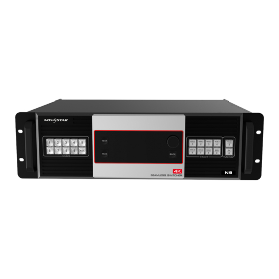
Page 4: Appearance
N9 Seamless Switcher User Manual Appearance Front Panel Button Function Input source buttons Indicate input source status or switch the layer input source. Status LEDs: On: The input source is accessed and in use. Dim: The input source is accessed but not in use. - Page 5 N9 Seamless Switcher User Manual Rear Panel Input INPUT-1 1x DP 1.1 Up to 3840×2160@30Hz input resolution For custom resolutions: Max. width: 3840 pixels Max. height: 4000 pixels HDCP 1.4 compliant Does not support interlaced signal inputs.
- Page 6 Max. width: 3840 pixels Max. height: 3840 pixels DL mode: The connectors are unavailable. HDMI 1x HDMI 1.3 Monitor the N9 input sources, VE7 input sources, PVW and PGM. 2x HDMI 1.3 Connect to auxiliary display devices, such as teleprompters. Control ETHERNET Connect to the control PC or network.
-
Page 7: Applications
N9 Seamless Switcher User Manual Applications N9 works independently N9 works with V-Can/C1 and VE7 www.novastar.tech... -
Page 8: Home Screen
Lock Denotes the lock/unlock status of front panel buttons. When the N9 is connected to the C1 or V-Can, the front panel buttons are locked automatically. Hold down the knob and ESC button to manually lock or unlock the front panel buttons. - Page 9 N9 Seamless Switcher User Manual Area Icon Description The device is connected to the control PC via Ethernet port. The device is not connected to the control PC. BKG enabled BKG disabled Output Test pattern Freeze Normal PGM edit PGM edit enabled...
-
Page 10: Menu Operations
Step 2 Press the knob to enter the input source screen. Step 3 Dual Link is selected by default. Press the knob to confirm the selection. Figure 5-2 Dual link 5.1.2 Standard EDID The N9 and VE7 support standard input resolution settings only. www.novastar.tech... -
Page 11: Custom Edid
N9 Seamless Switcher User Manual Step 1 On the Input Settings screen, rotate the knob to select an input source and press the knob to enter the input source screen. Step 2 Rotate the knob to select Standard EDID and press the knob to enter the standard EDID settings screen. -
Page 12: Limited To Full
RGB full. Output Settings 5.2.1 Output Mode The N9 supports both single link and dual link output modes. SL mode: DVI1, DVI2, DVI3 and DVI4 are used as single link connectors for mosaic output. -
Page 13: Output Resolution
DVI connectors mosaic output. Easy mosaic allows you to set Total Width and Total Height based on the screen size, and then the N9 will automatically calculate the width and height of each output connector and offers you a mosaic layout. -
Page 14: Advanced Mosaic
Step 5 Rotate the knob to select Apply and press the knob to confirm the settings. Figure 5-6 Advanced mosaic 5.2.5 Output Color The N9 supports output color settings. When you adjust the output color parameters, the settings will take effect in real time. Figure 5-7 Output color Layer Settings The N9 supports at most 7 layers. - Page 15 Off: Close the layer. Input Source Select or change the input source for the selected layer. When the N9 works with the VE7, the input source with an Ex in front of it is the input source of the VE7.
- Page 16 N9 Seamless Switcher User Manual Figure 5-10 Layer size and position H Width: Set the horizontal width of the layer. The default value is the half of the input source width. V Height: Set the vertical height of the layer. The default value is the half of the input source height.
-
Page 17: Bkg
7: The lowest priority (bottom layer) 5.3.2 BKG The N9 supports pure color BKG and BKG image. At most 8 BKG images are supported. On the main menu screen, go to Layer Settings > BKG and press the knob to enter the BKG settings screen. - Page 18 Step 3 Rotate the knob to select a BKG and press the knob to apply it to PVW. Figure 5-15 BKG image Pure Color BKG The N9 also supports pure color BKG. You can set the individual R, G and B values to set a pure color as the BKG. Figure 5-16 Pure color BKG Capture You can capture the displayed image on PGM or an input source image as the BKG.
-
Page 19: Layer Copy
If the AUX signal source is set to PGM or PVW and the source for capturing is PVW or PGM, the AUX display will flicker during BKG capturing. 5.3.3 Layer Copy The N9 supports the layer copying function. On the main menu screen, go to Layer Settings > Layer Copy and press the knob to enter the layer copying screen. -
Page 20: Dsk
When you move the original or copied layer, the two layers will move together vertically. 5.3.4 DSK The N9 supports the layer keying function (DSK). On the main menu screen, go to Layer Settings > DSK and press the knob to enter the layer keying screen. - Page 21 1.0s. Preset Settings The N9 supports up to 32 presets. User can save, load and clear the presets. On the main menu screen, rotate the knob to select Preset Settings and press the knob to enter the preset settings screen.
-
Page 22: Synchronization
AUX function is used for auxiliary output of any input source signal, PVW or PGM. It can send the unprocessed signal source to the connected display device. When the VE7 is connected to the N9, you can set the function of MVR/AUX connector of the VE7 via N9. Figure 5-25 AUX Step 1 On the main menu screen, go to Advanced Settings >... -
Page 23: Pgm Edit
N9 Seamless Switcher User Manual − Off: AUX display will not be switched during preset switching. Follow Screen FTB: − On: When the LED screen fades to black, AUX screen will also fade to black. − Off: When the LED screen fades to black, AUX screen will display the image normally. -
Page 24: Factory Reset
When the device is connected to the control PC via both USB and LAN cables, you can select LAN Preferred (default) or USB Preferred. When LAN Preferred is selected, the N9 is controlled by the control PC via the LAN cable. When USB Preferred is selected, the N9 is controlled by the control PC via the USB cable. - Page 25 IP addresses of other devices to avoid network conflict. You can select Reset to reset the IP Address and Subnet Mask to the defaults. Language Currently the N9 supports English and Chinese. You can change the UI language as required. Figure 5-30 Language www.novastar.tech...
-
Page 26: Can Control
When multiple N9 units are connected to V-Can, the control PC where V-Can is installed must be on the same LAN with the N9 units. V-Can will automatically search all the N9 units on this LAN and connect all of them. -
Page 27: C1 Control
Step 1 Perform the device connections described in 3 Applications. Note: When multiple N9 units are connected to the C1, the C1 must be on the same LAN with the N9 units. Step 2 On the home screen, click Configuration to enter the configuration page, and then click Search. - Page 28 N9 Seamless Switcher User Manual Figure 7-3 Device list Step 4 Click next to the device IP address to enter the device properties screen. Figure 7-4 Device properties Input: Set the input resolution and input color. Output: Set the output resolution and output color.
- Page 29 N9 Seamless Switcher User Manual Step 6 Select a layer by pressing a layer button in the LAYER area on the front panel. You can adjust the layer position, size and priority by using the joystick. Step 7 Press the TAKE or CUT button, or push T-Bar to send PVW to PGM.
-
Page 30: Specifications
N9 Seamless Switcher User Manual Specifications Connector Specifications Connector Resolutions 800×600@50/60/75/120Hz 1920×1080@50/60/75/120Hz 1024×768@50/60/75/120Hz 1920×1200@/50/60/75Hz 1280×720@50/60/75/120Hz 2048×640@50/60/75/120Hz 1280×768@50/60/75/120Hz 2048×1152@/50/60/75Hz 1280×800@50/60/75/120Hz 2048×1536@/50/60/75Hz DP 1.1 1280×1024@50/60/75/120Hz 2304×1152@/50/60/75Hz 1366×768@50/60/75/120Hz 2560×816@50/60/75/120Hz 1440×900@50/60/75/120Hz 2560×960@/50/60/75Hz 1600×1200@50/60/75/120Hz 2560×1600@/50/60Hz 1680×1050@50/60/75/120Hz 3840×1080@/50/60Hz 800×600@50/60/75/120Hz 1920×2160@50/60/75/120Hz 1024×768@50/60/75/120Hz 2048×640@50/60/75/120Hz 1280×720@50/60/75/120Hz 2048×1152@50/60/75/120Hz 1280×768@50/60/75/120Hz 2048×1536@50/60/75/120Hz 1280×800@50/60/75/120Hz... - Page 31 N9 Seamless Switcher User Manual Electrical Power connector AC100V–240V~50/60Hz Specifications Power consumption 95 W Operating Operating 0° C to 50° C Environment temperature Operating humidity 20% RH to 90% RH –20° C to +60° C Storage temperature Physical Dimensions 482.6 mm × 139 mm × 411.5 mm...
Need help?
Do you have a question about the N9 and is the answer not in the manual?
Questions and answers