
Related Manuals for BEKA BA488CF-P PROFIBUS PA


Summary of Contents for BEKA BA488CF-P PROFIBUS PA
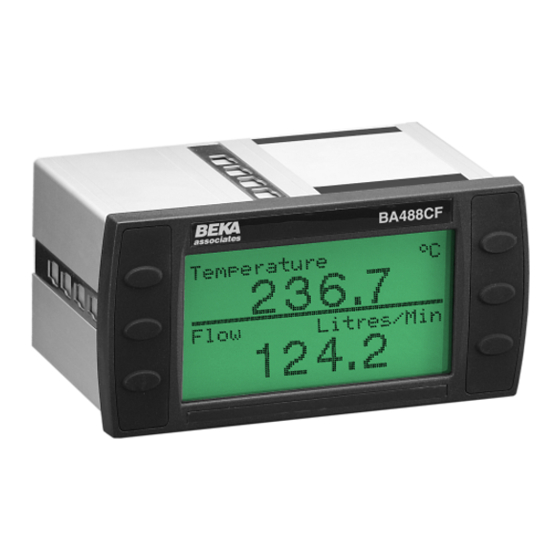
- Page 1 BA488CF-P PROFIBUS PA Intrinsically safe Panel mounting Fieldbus Display issue 3 Issue: 3 December 2011...
-
Page 2: Table Of Contents
CONTENTS 1. Description 7. Maintenance 1.1 Documentation 7.1 Fault finding during commissioning 1.2 Version 3.0 firmware 7.2 Fault finding after commissioning 7.3 Servicing 7.4 Routine maintenance 7.5 Guarantee 2. Operation 2.1 Controls 7.6 Customer comments 3. Intrinsic Safety Certification 8. Accessories 3.1 ATEX certificate 8.1 Tag number 3.2 Zones, gas groups and T rating... -
Page 3: Description
November 2009 which The instrument has been certified intrinsically safe may be downloaded from the obsolete products by European Notified Body Intertek Testing section of the BEKA website. Services (ITS) to the ATEX Directive 94/9/EC for use in explosive gas atmospheres. -
Page 4: Operation
2. OPERATION Fig 1 shows a simplified block diagram of the BA488CF-P PROFIBUS display. When the optional alarms and external switches are not used, the instrument only requires a two-wire connection to the fieldbus. How much of the BA488CF-P PROFIBUS display configuration can be performed via the fieldbus depends upon the system host. -
Page 5: Intrinsic Safety Certification
(FISCO) defined in EN 60079 Part 27, which standards specified may have subsequently been simplifies intrinsic safety system design. deharmonised, please see BEKA Declaration of Conformity for current conformity. The BA488CF-P may also be connected to non FISCO compliant fieldbus segments by using the entity concept to assess safety. -
Page 6: Alarm Outputs
It shows the 0.58W ATEX certification information, a statement that the instrument is a FISCO Field Device, plus BEKA The switches and associated wiring connected to associates name and location. Non European the terminals must comply with the requirements certification information may also be included. -
Page 7: Non Fisco Sysems
4.2 Non FISCO Systems If the BA488CF-P PROFIBUS display is to be connected to a fieldbus segment that does not comply with FISCO requirements, the safety parameters power supply PROFIBUS Display must be compared using the entity concept. The maximum output safety parameters of the device powering the fieldbus segment must be equal to, or less than, the input safety parameters of terminals 1 &... -
Page 8: Installation
5. INSTALLATION 5.2 Installation Procedure a. Insert the BA488CF-P into the instrument 5.1 Location The BA488CF-P PROFIBUS display is housed in a panel cut-out from the front of the panel. robust aluminium enclosure with a toughened glass window mounted in a Noryl bezel. The front b. -
Page 9: Emc
5.3 EMC The BA488CF-P complies with the requirements of the European EMC Directive 2004/108/EC. specified immunity all wiring should be in screened twisted pairs with the screens connected to the potential equalising network as recommended in EN 60079-14. -
Page 10: Display & Alarm Configuration
Operating push buttons 6. DISPLAY & ALARM CONFIGURATION In addition to loading the BA488CF-P PROFIBUS simultaneously accesses the display configuration display GSD files onto the system host and menu. If the BA488CF-P is not protected by an defining up to eight fieldbus variables that are to be access code the main menu will be displayed. -
Page 11: Configurable Functions
PROFIBUS Fieldbus Interface Guide which downloaded from the BEKA website. One variable + vertical bargraph This sub-menu allows one of eleven standard display formats to be selected. The standard formats contain one, two, three, four or eight fieldbus variables some with bargraphs as shown below. -
Page 12: Input Settings
6.3.2 Input Settings 6.3.3 Tags Each of the eight fieldbus variable inputs may be Each of the eight fieldbus variables may be scaled before being displayed as shown below. displayed with an individual tag that can contain up to sixteen alphanumeric characters. This menu Display = (Gain x Fieldbus variable) + Offset allows these tags to be entered. -
Page 13: Alarm Activation
6.3.5.2 Alarm Activation 6.3.6.3 Access Code PROFIBUS variables that have not been validated Defines a four digit alphanumeric code that must are displayed with dark characters on a light be entered to gain access to the Quick Access background, and some screen formats also Menu. -
Page 14: Unit Info
6.3.8 Code 6.4 Quick Access Menu Defines the four digit alphanumeric code that must The Quick Access Menu allows an operator to be entered to gain access to the instrument adjust the backlight brilliance and the display configuration menus. Alpha characters are case contrast without having access to the other sensitive. -
Page 17: Maintenance
Wrong variable Wrong screen Other screens by We recommend that faulty BA488CF-P Fieldbus displayed selected operating Up or Displays are returned to BEKA associates or to our Down button local agent for repair. Display shows Display Number Format ‘?????’ Overange see section 6.3.2... -
Page 18: Accessories
The BA488CF-P can be supplied with a thermally printed tag number on the rear panel. This tag number is not visible from the front of the instrument after installation. 8.2 PROFIBUS Interface Guides The BEKA PROFIBUS Interface Guide, which may downloaded from website www.beka.co.uk contains configuration information for all BEKA PROFIBUS products. -
Page 19: Index
9. INDEX Subject Section Subject Section Address 6.3.11 Notified Body 1; 3.1 Alarms 6.3.5 Number Format 6.3.2 Activation 6.3.5.2 Output 3.5; 6.3.5.3; 4.4 Programming Summary 6.3.5.1 Guide 7; 9.2 PROFIBUS PA 1; 2 ATEX Directive Quick access menu 6.3.6.2; 6.4 Backlight 6.3.6.1 Bargraph Limits... - Page 20 Installations must comply with safe and nonincendive by FM Approvals, project the BEKA associates Control Drawing CI480-18, identification 3022546. Copies of the Certificate of which is attached to this Appendix, and with the Compliance are available from BEKA associates.
- Page 29 For additional information about the IECEx certification scheme and to view the BEKA associate certificates, please visit www.iecex.com A2.1 IECEx Certificate of Conformity The BA488CF-P Fieldbus Display has been issued with an IECEx Certificate of Conformity number IECEx ITS 05.0007 which specifies the following...
Need help?
Do you have a question about the BA488CF-P PROFIBUS PA and is the answer not in the manual?
Questions and answers