
Subscribe to Our Youtube Channel
Related Manuals for Kratki PIRAMIDE


Summary of Contents for Kratki PIRAMIDE
- Page 1 CALENTADOR DE JARDÍN DE GAS/ PIRAMIDE Instrucciones de instalación y funcionamiento Producent: www.kratki.com Kratki.pl Marek Bal ul. W. Gombrowicza 4 26-660 Wsola/Jedlińsk...
- Page 2 Wspieramy kampanię Nie Rób Dymu www.nierobdymu.com, fb/nierobdymu PARA EL INSTALADOR: Deje el manual con el dispositivo. PROPIETARIO (CONSUMIDOR): Guarde este manual para uso futuro. INSTALATORA: Zostawić instrukcję razem z urządzeniem. WŁAŚCICIEL (KONSUMENT): Zachowaj niniejszą instrukcję do przyszłego użytku.
- Page 3 Lea las instrucciones cuidadosamente. Si tiene alguna pregunta o reserva, comuníquese con nuestro departamento técnico. Toda la información adicional está disponible en nuestro sitio web www.kratki.com. Kratki.pl Marek Bal es un productor conocido y respetado de dispositivos de calefacción tanto en el mercado polaco como en el europeo.
- Page 4 El manual debe conservarse durante toda la vida útil del dispositivo. El calentador de jardín de gas PIRAMIDE ha sido diseñado para suministrar propano o una mezcla de gases propano butano. Este dispositivo está disponible en varias versiones según las opciones de control, el tipo de acristalamiento o las preferencias de color.
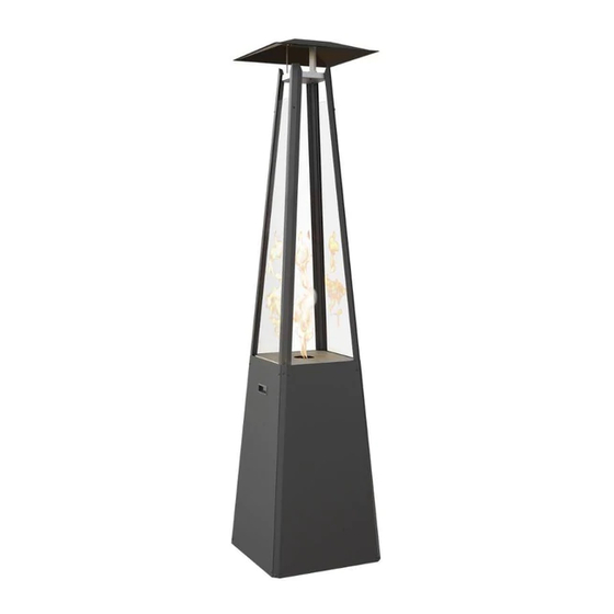
- Page 5 Ogrzewa Fig. 2. Dibujo acotado del calentador de jardín a gas PIRAMIDE...
-
Page 6: Especificaciones Técnicas
Marca / Boquilla de gas LPG 1.70 1.90 1.70 1.60 1.70 1.60 1.50 Tabla 1. Especificaciones técnicas - PIRAMIDE DATOS DEL FABRICANTE Podructor: Kratki.pl Marek Bal Kratki.pl Marek Bal Datos de contacto: ul. Gombrowicza 4, 26-660 Wsola, Polska tel. +48 48 384 44 88 fax +48 48 384 44 88 www.kratki.com... -
Page 7: Instalación
INSTALACIÓN EL CALENTADOR DE GAS PIRAMIDE DEBE SER INSTALADO Y / O REPARADO POR UN ESPECIALISTA CUALIFICADO. NO INTENTE MODIFICAR LA CONSTRUCCIÓN DE LA MÁQUINA O SUS COMPONENTES. CUALQUIER MODIFICACIÓN CAUSARÁ PÉRDIDA INMEDIATA DE GARANTÍAS Y CERTIFICADOS. TENGA EN CUENTA: ACERCA DE LAS RECOMENDACIONES DE ESTAS INSTRUCCIONES CON RESPECTO A LA INSTALACIÓN, OPERACIÓN O RAZONAMIENTO DE LAS RECOMENDACIONES... - Page 8 Debido a la posibilidad de altas temperaturas, especialmente en el vidrio del dispositivo, todos los materiales inflamables deben ubicarse a una distancia segura del dispositivo. Los niños mayores y otras personas inconscientes deben ser informados y advertidos de la posibilidad de que se produzcan altas temperaturas en el dispositivo durante su funcionamiento e inmediatamente después de su extinción, y deben evitar el contacto con el dispositivo para evitar quemaduras e ignición de la ropa.
- Page 9 El calentador de gas para jardín PIRAMIDE ha sido diseñado pensando en su comodidad. El dispositivo está equipado con un moderno sistema de control de gas para proteger contra fugas de...
-
Page 10: Normas De Instalación
El dispositivo tiene una cámara de combustión abierta sin la opción de conectarlo a una chimenea. El calentador de gas para jardín PIRAMIDE se vende con el sistema de control de control de gas pre- instalado, sin embargo, antes del primer uso se recomienda verificar la estanqueidad del sistema debido a la posibilidad de que se suelte en el transporte. - Page 11 Paso 1. La base del quemador (2) debe instalarse de modo que el logotipo de Kratki.pl apunte en la misma dirección que el orificio en la base del cuerpo (1). Luego atornille los soportes (13) con la base...
- Page 12 Paso 2. Atornille los soportes (5) al cuerpo y al radiador (6) como se muestra en la figura a continuación.
- Page 13 Paso 3. Atornille la caja con el quemador y la válvula de control (7), y luego coloque la cubierta del quemador (10) como se muestra en la figura a continuación.
- Page 14 Paso 4. Atornille los imanes (16) con la arandela del imán (9) a los ángulos inferiores (13) desde el lado recortado en la base, como se muestra en la figura a continuación.
- Page 15 Paso 5.
- Page 16 Paso 6. Atornille las cubiertas laterales (12) e inserte la puerta (4), deslizándolas en la muesca en la base del dispositivo. Rys. 3. Schemat montażu ogrzewacza ogrodowego UMBRELLA...
- Page 17 PARAGUAS / BS Paso 1. Instale la base del quemador (2) con el logotipo de Kratki.pl en la misma dirección que el orificio en la base del cuerpo (1). Luego atornille los soportes (13) con la base del quemador y la base...
- Page 18 Paso 2. Atornille el vidrio (8.2) y el disipador de calor (8.12) a la base del quemador usando el mango y el tornillo según el diagrama a continuación. Fig. 4. Diagrama de instalación del calentador de jardín PIRAMIDE / BS 18...
- Page 19 ELEGIR LA UBICACIÓN DEL CALENTADOR DE JARDÍN DE GAS El calentador de jardín a gas PIRAMIDE es un dispositivo móvil capaz de moverse a cualquier lugar seleccionado. Sin embargo, hay restricciones que deben seguirse estrictamente. El dispositivo, debido a la posibilidad de altas temperaturas en sus superficies externas, debe mantenerse alejado de materiales inflamables, y también debido a la cámara de combustión abierta sin la posibilidad de...
- Page 20 REQUISITOS PARA EL ÁREA ALREDEDOR DEL CALENTADOR DE JARDÍN DE GAS DE MATERIALES INFLAMABLES El calentador de gas para jardín PIRAMIDE ha sido probado y aprobado para calentar espacios abiertos o bien ventilados sujetos a distancias seguras de materiales inflamables, como se muestra en los diagramas a continuación.
- Page 21 El espacio indicado arriba es el espacio libre mínimo de materiales inflamables, a menos que esto sea eliminado por otra entrada. El incumplimiento de las autorizaciones anteriores (espacio libre) puede provocar un incendio. ¡¡¡ATENCIÓN !!! Está absolutamente prohibido usar el calentador de gas para jardín en un espacio abierto durante la precipitación ATMOSFÉRICA.
-
Page 22: Primera Puesta En Marcha
PRIMERA PUESTA EN MARCHA Antes del primer uso, asegúrese de que todas las conexiones de los componentes individuales del sistema se hayan realizado de acuerdo con las instrucciones contenidas en el manual. La conexión incorrecta del sistema de control de gas puede provocar daños. Durante las primeras igniciones, un olor específico puede ser perceptible, persistiendo incluso durante varias horas después de usar el dispositivo. - Page 23 Fig. 7. Diagrama de conexión para el sistema de control de gas manual CONEXIÓN A LA FUENTE DE GAS (BOMBONAS) ATENCIÓN: Para conectar el dispositivo a una bombona de gas, el cliente debe comprar y conectar al menos una manguera flexible de 60 cm con un certificado CE y GAR válido con conectores forjados, una manguera flexible con una trenza de malla de acero o una manguera flexible de acero.
- Page 24 Todas las conexiones deben ser realizadas por un técnico cualificado y solo con el dispositivo apagado y desconectado del suministro de gas. Conecte el regulador a la bombona asegurándose de que los sellos estén en su lugar (consulte el diagrama anterior), si los sellos son viejos o están dañados o si falta uno de ellos, el dispositivo no puede usarse hasta que se reemplacen los sellos.
- Page 25 PRECAUCIÓN: Debe recordarse que la bombona de gas montado dentro del dispositivo debe estar unido con una cuerda con mosquetones a los soportes inferiores como se muestra en la siguiente figura: Fig. 8. Dibujo explicativo de los soportes inferiores dela bombona de gas al que se debe unir la bombona después de la instalación.
- Page 26 4. Después de encender el quemador de control, mantenga el interruptor en esta posición durante 5 segundos hasta que el termopar se caliente, luego suelte el interruptor en sentido contrario a las agujas del reloj hasta la posición final: la potencia nominal del calentador (esto también iniciará el flujo de gas al quemador principal) .
-
Page 27: Mantenimiento
Paso 2. Baja llama El interruptor está en la posición de disparo del quemador de control (pos. 2). El gas fluye hacia el quemador principal con la configuración de potencia mínima. Llama alta El interruptor está en la posición de disparo del quemador de control (pos. 2). Para aumentar la potencia al nivel de potencia máxima y, por lo tanto, también a la altura de la llama, o a cualquier potencia intermedia entre la potencia mínima y máxima, gire el interruptor en sentido antihorario hasta que se bloquee. - Page 28 Lista de verificación: Acciones Realice el procedimiento de encendido en el calentador. Verifique el funcionamiento de todos los sistemas de seguridad. Control general Compruebe si la llama del quemador principal arde de manera constante. Compruebe que el quemador principal arde de manera uniforme. Verifique las conexiones de gas por fugas.
-
Page 29: Proteccion Del Medio Ambiente
PROTECCION DEL MEDIO AMBIENTE - Todos los componentes de embalaje en los que se ha suministrado el calentador de gas deben eliminarse de manera adecuada. - Si el dispositivo se ha agotado, deséchelo. El usuario está obligado a pasar la chimenea a la institución correspondiente que se ocupa del reciclaje de este tipo de equipos. - Page 30 The device must be installed and serviced only by a qualified installer. Thank you for purchasing the PIRAMIDE gas garden heater. This device has been designed with your safety and comfort in mind. We express confidence that you will be satisfied with your cho-ice due to the commitment we have put in the work on the design and production of this device.
- Page 31 This manual contains all the information necessary for the correct connection, operation and main- tenance of the PIRAMIDE gas garden heater designed for use in an open or well ventilated space. PIRAMIDE as a gas fueled device is an open device, without an exhaust system, intended for heating exposed and / or ventilated surfaces.
- Page 32 Ogrzewa Fig. 2. Dimensional drawing of the PIRAMIDE/ BS versions.
-
Page 33: Technical Specification
Gas nozzle mark LPG 1.70 1.90 1.70 1.60 1.70 1.60 1.50 Table 1. Technical specification - PIRAMIDE Manufacturer details: Manufacturer: Kratki.pl Marek Bal Contact details: Kratki.pl Marek Bal ul. Gombrowicza 4, 26-660 Wsola, Polska tel. +48 48 384 44 88 fax +48 48 384 44 88 www.kratki.com... -
Page 34: Installation
INSTALLATION PIRAMIDE GAS OUTDOOR HEATER MUST BE INSTALLED AND / OR SERVICED BY A QUALIFIED SPE- CIALIST. DO NOT ATTEMPT TO MODIFY THE CONSTRUCTION OF THE DEVICE OR ITS COMPONENTS. ANY MODIFICATION WILL CAUSE IMMEDIATE LOSS OF WARRANTIES AND CERTIFICATES.PLEASE NOTE: AVOID THE RECOMMENDATIONS OF THESE INSTRUCTIONS WITH... - Page 35 Due to the possibility of high temperatures of all surfaces of gas garden fireplaces and due to po- ssible exposition to the fire, all flammable materials should be located at a safe distance from the device. Elderly people, children and other unconscious persons should be informed and warned of the possibility of high temperatures occurring on the appliance during its operation and immediately after it is extinguished, and should avoid contact with the appliance to prevent burns and ignition of clothing.
- Page 36 7 or on your appliance’s rating label. The PIRAMIDE gas garden heater has been designed with your comfort in mind. The device is equip- ped with a modern gas control system protecting against uncontrolled gas leakage.
-
Page 37: Installation Introduction
This appliance has been tested for quality and safety and has been certified by a notified testing la- boratory. WARNING The PIRAMIDE gas garden heater is adapted to work with a cylinder or a household tank of a propane-butane gas mixture. The flexible connection pipe should be intended for LPG from the cylinder. - Page 38 UMBRELLA VERSION Step 1. The Base of the burner (2) shall be installed with the logo of Kratki.pl in the same direction as the hole in the base of the body (1). Then screw in the angles (13) with both burner base and body...
- Page 39 Step 2. Screw the angles (5) with the existing body and a cap (6) as per drawing below.
- Page 40 Step 3. Screw the box with the burner and control valve (7) and then place a burner cover (10) as per drawing below.
- Page 41 Step 4. Screw the magnets (16) with the magnet washer (9) to the bottom angles (13) from the notch in the base side as per drawing below.
- Page 42 Step 5.
- Page 43 Step 6. Screw the side covers (12) and put the door (4) in buy sliding them into the cutout in the base of the appliance. Fig. 3. Installation diagram of the UMBRELLA gas outdoor heater...
- Page 44 PIRAMIDE / BS VERSION Step 1. The Base of the burner (2) shall be installed with the logo of Kratki.pl in the same direction as the hole in the base of the body (1). Then screw in the angles (13) with both burner base and body...
- Page 45 Step 2. Screw the glasses (8.2) and the radiator (8.12) to the burner base using the mounts and screws as per diagram below. Fig. 4. Installation diagram of the PIRAMIDE/BS gas outdoor heater...
- Page 46 CHOOSING THE LOCATION OF THE GAS OUTDOOR HEATER The PIRAMIDE gas garden heater is a mobile device capable of movement to any place of your choice. However, there are restrictions that must be strictly followed. The device, due to the possibility of...
-
Page 47: Moving Of The Appliance
PIRAMIDE gas garden heater has been tested and approved for heating open or well ventilated spaces, subject to safe distances from flammable materials, as shown in the diagrams below. - Page 48 The space indicated above is the minimum free space from flammable materials, unless this is removed by another entry. Failure to observe the above clearances (free space) may result in a fire. ATTENTION!!! It is absolutely prohibited to use a gas garden heater in an open space during ATMOSPHERIC precipitation.
-
Page 49: First Start
FIRST START Before first use, make sure that all connections of individual system components have been made in accordance with the instructions contained in the manual. Incorrect connection of the gas control system may result in its damage. During the first few ignitions a specific smell may be perceptible, persisting even for several hours after using the device. - Page 50 Fig. 7. Connection diagram for the manual gas control system CONNECTION TO THE GAS SOURCE (GAS BOTTLES/CYLINDERS) ATTENTION: To connect the appliance to the gas cylinder customer has to buy and connect at least 60 cm CE and GAR approved flexible hose with forged connectors, flexible hose with steel mesh braid or flexible steel hose.
- Page 51 All connections shall be made by a qualified serviceman and only on a not working, disconnec- ted from the gas supply, appliance. Connect the regulator to the cylinder making sure that the seals are in place (See diagram above), if the seals are old or damaged or if one of them is missing, the device cannot be used until the seals are replaced.
-
Page 52: Operation
ATTENTION: Please note that the gas cylinder while installed inside the appliance has to be fasteneed with a cord with a carabiners to the bottom brackets as per drawing below: Fig. 8. An overview of the of the bottom brackets. OPERATION The user choosing the gas outdoor heater receives a device equipped with a manual controller. - Page 53 5. The adjustment is done by turning the knob from the final position (maximum power) to the firing up position of the pilot burner (minimum power). Turning off the appliance: 1. Turn the knob to the control torch firing position clockwise. 2.
- Page 54 Pos. 2. Low flame The knob is in the firing position of the pilot burner (pos. 2). Gas flows to the main burner at minimum power settings. High flame The knob is in the firing position of the pilot burner (pos. 2). To increase the power to the maximum power level, and thus also the flame height, or to any intermediate power between the minimum and maximum power, turn the knob counterclockwise until it locks.
- Page 55 Checklist: L.p Scope Actions Perform firing up procedure of your gas garden fireplace. Check the operation of all security systems. General control Check if the main burner flame burns steadily. Check that the main burner burns evenly. Check the gas connections for leaks. Check that the cylinder chamber ventilation is not blocked.
-
Page 56: Environmental Protection
ENVIRONMENTAL PROTECTION - All packaging components in which the gas garden fireplace has been supplied should be disposed of in a manner appropriate to their type. - If the device is used up again, it must be disposed of. The user is obliged to pass the fireplace to the appropriate institution dealing in the recycling of this type of equipment. - Page 60 Kratki.pl Marek Bal ul. Gombrowicza 4, Wsola, 26-660 Jedlińsk, Poland tel. 00 48 48 389 99 00, 00 48 48 384 44 88, fax 00 48 48 384 44 88 wew. 106 www.kratki.com AP/11/2019...
Need help?
Do you have a question about the PIRAMIDE and is the answer not in the manual?
Questions and answers