Table of Contents
Advertisement
Quick Links
Advertisement
Table of Contents

Related Manuals for ELNet Pico 5


Summary of Contents for ELNet Pico 5
- Page 1 ElNet 5/60 Pico Energy Powermeter Rev 1.3...
-
Page 2: Table Of Contents
Mechanical mounting ..........14 Wiring Schematics ..........15 Connections ............17 Manufacturing Data..........20 CHAPTER 3 — USING ElNet Pico Powermeter ... 21 Front Panel ............. 21 Control Buttons ............22 CHAPTER 4 - NECESSARY ElNet Pico SETTINGS ..23 Settings for Current Transformer ...... - Page 3 Time Settings ............27 Date Settings ............28 Filter Settings ............29 CHAPTER 5 — Text Panel Displays ........30 Current ..............30 Current in Neurtal Line ........31 Voltage ..............31 Active Power (P) ............ 32 Reactive Power (Q) ..........34 Apparent Power (S) ..........
- Page 4 6.1.4 Function Field ............. 44 6.1.5 Data Field ............45 6.1.6 Check Field............45 Registers for ElNet Pico Multimeter ....45 6.2.1 Registers addresess ..........47 Communication Connections ........ 47 Communication Settings ........47 6.4.1 Communication Address ........48 6.4.2 Baud Rate ............48 6.4.3 Parity ..............
-
Page 5: Chapter 1 ─ Introduction
CHAPTER 1 ─ INTRODUCTION 1.1 About the ElNet Pico Powermete Large consumers of electricity e.g. factories, hotels, hospitals, municipalities, need to know the history of their consumption and the quality and the values of the power supply. Details such as... -
Page 6: How To Use This Manual
There could be a situation where two of the above mentioned tasks can be combined, or in a rare instance one person could handle all three tasks. ElNet Pico CHAPTER 1, Introduction, describes the Powermeter its potential users, the readings it can provide and some of its features in brief. -
Page 7: Safety Information
CHAPTER 5, Front Panel Displays, is an easy to follow step-by- step guide to obtain readings and tables. CHAPTER 6, Communications provides details about the Communication capabilities of the ElNet Pico Energy Powermeter , and how to Set Up. CHAPTER 7, Specifications, is a detailed list of specifications of... -
Page 8: Warranty
CONTROL APPLICATIONS Ltd does not accept liability for any damage that may be caused by natural disasters (such as floods, fire, earthquake, lightening etc.). CONTROL APPLICATIONS Ltd does not accept liability for any damage that may be caused by malfunction of the ElNet Pico Energy Powermeter. - Page 9 CONTROL APPLICATIONS Ltd will advise the customer on the proper installation and use of the ElNet Pico Energy Powermeter but will not accept any responsibility that the instrument is suitable for the application for which it was originally purchased. This warranty may become void if the Installation, Parameter Configuration &...
-
Page 10: Your Comments Are Welcome
1.5 Your comments are welcome CONTROL APPLICATIONS Ltd. sincerely thanks you for choosing our ElNet Pico Energy Powermeter We are confident that it will provide you with many years of trouble free service and give you all the power and energy information and history that you expected from the instrument when you bought it. -
Page 11: Disclaimer
1.6 Disclaimer Information in this User Manual is subject to change without notice and does not represent a commitment on the part of CONTROL APPLICATIONS Ltd. CONTROL APPLICATIONS Ltd supplies this User Manual as is without warranty of any kind; either expressed or implied, and reserves the right to make improvements and/or changes in the manual or the product at any time. -
Page 12: Chapter 2 - Installation
Refer to Section 1.3 Safety information before carrying out any installation. Read this manual thoroughly and make sure you understand the contents before connecting the ElNet Pico Energy Powermeter to any power source. -
Page 13: Contents Of Packaging
Elnet Pico Energy Powermeter To unpack the The Elnet Pico Energy Powermeter is packed and shipped in a carton approximately 19x11x6.5 cm. Before opening the package, ensure the area, clean and dry. Without using any sharp instruments, carefully open the carton of the Elnet Pico Energy Powermeter. -
Page 14: Mechanical Mounting
Allow sufficient space to carry out maintenance to the ElNet Pico Energy Powermeter The ElNet Pico Energy Powermeter is manufactured with a standard DIN rail mounting. To mount, simply choose a suitable location and click into position. Figure 2.1 Din Rail Mounting Diagram... -
Page 15: Wiring Schematics
2.3 Wiring Schematics ElNet Pico 5 Energy Powermeter To wire up the Figure 2.2 Schematic Wiring Diagram... - Page 16 ElNet Pico 60 Energy Powermeter To wire up the Figure 2.2 Schematic 60A Wiring Diagram...
-
Page 17: Connections
All Connections are made via terminal connector plugs (Voltage input, Power Supply, etc.). Recommended max. tightening torque for the connector screws is 0.5 Nm. The CT cores of the ElNet Energy Powermeter a re located internally in the instrument and the lead from the leg of the external Current Transformer must be connected to the correct terminal connector in order to maintain the correct direction. - Page 18 Transformer leads. Repeat the procedure for Line 2 and Line 3. Connect the rest of the connections to the ElNet Pico Energy Powermeter by means of terminal connector plugs. The Front Panel (See Figure 2.3) has all connections printed and is simple to follow.
- Page 19 Description Remarks Designation Line1 Supplied Voltage Through a 6Amp fuse Line2 Supplied Voltage Through a 6Amp fuse Line3 Supplied Voltage Through a 6Amp fuse Neutral Measurement neutral Line From Current Note the correct direction to Transformer L on Line1 insert the lead From Current Note the correct direction to Transformer K on...
-
Page 20: Manufacturing Data
2.5 Manufacturing Data. 2.5.1 From the main menu, use the buttons to scroll to Config menu and press “Enter”. C o n f i g E n e r g y 2.5.2 In the "PassWord…" menu use the buttons to change the password to 1 and press “Enter”. -
Page 21: Chapter 3 - Using Elnet Pico Powermeter
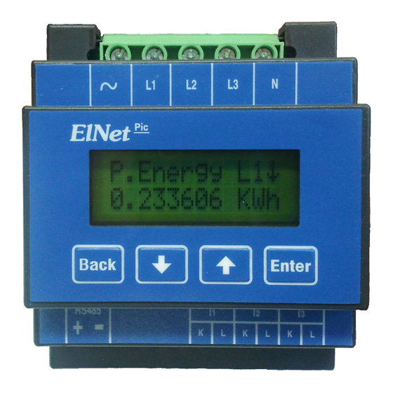
CHAPTER 3 — USING ElNet Pico Powermeter In this chapter you will find descriptions and functions of the front panel and the control buttons and how to use them. 3.1 Front Panel To operate the front panel: The Front Panel has a graphic screen and 3 operating buttons. -
Page 22: Control Buttons
3.2 Control Buttons To operate the Control Buttons on Front Panel: The ElNet Pico Energy Powermeter has Four Control Buttons. With these buttons the User and Senior Electrical Engineer can achieve all the functions necessary. The Control Buttons are arranged on a keypad below the display screen and require slight finger pressure to click. -
Page 23: Chapter 4 - Necessary Elnet Pico Settings
NECESSARY ElNet Pico SETTINGS CHAPTER 4 - In this chapter you will find instructions to set the minimum settings that are necessary to allow the ElNet Pico Energy Powermeter to function properly. WARNING! The selection, installation and settings of the... -
Page 24: Settings For Current Transformer
NOTE! The most important setting necessary for the proper functioning of the ElNet Pico Energy Powermeter is the Current Transformer setting. The cross section of the leads to the current Transformer must be compatible to the power of the current transformer. -
Page 25: Phase Order Check
4.2 Phase Order Check NOTE! To avoid any problems arising from incorrect Voltage Connections or accidental reversal of Current Transformer Connections, it is necessary to perform a Phase Order Check before continuing. To perform Line Status Check (Connection Check) & Phase Order Check: 4.1.1 From the Main Menu roll to Config and press “Enter”. - Page 26 4.1.4 The Line Status & Phase Order screen appears. V o l t L i n e 1 : O K V o l t l i n e 2 : O K 4.1.5 Click buttons to Roll Volts Line1,2 & 3. 4.1.6 Click buttons to Roll Curr.
-
Page 27: Time Settings
4.3 Time Settings To set Time: 4.3.1 See Section 4.1 for instructions to arrive at the Configuration Menu. From the Configuration Menu scroll to Set Time and click “Enter”. S e t T i m e S e t D a t e 4.3.2 The Set Time screen appears, to allow access to set time press “Enter”. -
Page 28: Date Settings
4.4 Date Settings To set Date: 4.4.1 See Section 4.1 for instructions to arrive at the Configuration Menu. From the Configuration Menu scroll to Set Date and click “Enter”. S e t D a t e C T C o n f i g u r e 4.4.2 The Set Date screen appears, to allow access to set date press “Enter”. -
Page 29: Filter Settings
4.5 Filter Settings All readings in the ElNet Energy Powermeter are read and displayed every second. In a “noisy” system these readings would show wild fluctuations. Fluctuations can be “smoothed” out by applying Time Average Filters. Time Average Filters utilizes the “Sliding Window” method. A... -
Page 30: Chapter 5 - Text Panel Displays
CHAPTER 5 — Text Panel Displays In this chapter you will find instructions on how to obtain the readings that the ElNet Energy Powermeter provides, e.g., Current, Voltage Power, Power Factor and Energy. 5.1 Current To display Current for all 3 Phases: 5.1.1 From the Main Menu roll to General and press “Enter”. -
Page 31: Current In Neurtal Line
5.2 Current in Neurtal Line By using Vector calculations the ElNet Energy Powermeter calculates the Current in the Neutral Line. To display Current in Neutral Line: Repeat Steps 1 to 3 as found in Section 5.1. Roll to Current In Neutral line. -
Page 32: Active Power (P)
The Voltage Screen Appears V o l t a g e L 1 0 0 0 . 0 5.3.3 Roll to Voltage Line 2, Line 3 and to Voltage between Line 1-2, Line 2-3 and Line 3-1. 5.3.4 When finished press “Back” to return to General Menu. Parameter Description Units... - Page 33 5.4.2 Roll to P. Power and press “Enter”. P . P o w e r Q . P o w e r 5.4.3 The Active Power Screen Appears. P . P o w e r L 1 0 . 0 5.4.4 Roll to Active Power Line 2, Line 3, ALL.
-
Page 34: Reactive Power (Q)
5.5 Reactive Power (Q) To display Reactive Power for all 3 phases: 5.5.1 From the Main Menu roll to Power and press “Enter”. P o w e r C o n f i g 5.5.2 Roll to Q. Power and press “Enter”. Q . -
Page 35: Apparent Power (S)
5.6 Apparent Power (S) To display Apparent Power for all 3 phases: 5.6.1 From the Main Menu roll to Power and press “Enter”. P o w e r C o n f i g 5.6.2 Roll to S. Power and press “Enter”. S . -
Page 36: Total Power Factor And For Each Phase
5.7 Total Power Factor and for each Phase To display Power Factor for all 3 phases: 5.7.1 From the Main Menu roll to General and press “Enter”. 5.7.2 Roll to Pwr Factor and press “Enter”. P w r F a c t o r F r e q u e n c y 5.7.3 The Power Factor Screen Appears. -
Page 37: Active Energy
P . E n e r g y L 1 0 . 0 0 0 K W h 5.9.4 Roll to Active Energy Line 1, Line 2, Line 3, ALL. The Export Energy (opp. Direction) can be read via communicatoin. (Please check the Elnet Comm file). -
Page 38: Reactive Energy
5.10 Reactive Energy To display Reactive Energy for all 3 phases: 5.10.1 From the Main Menu roll to Energy and press “Enter”. 5.10.2 Roll to Reactive Energy and press “Enter”. Q E n e r g y S E n e r g y 5.10.3 The Reactive Energy Screen Appears. -
Page 39: Energy
Total Apparent Energy for all 3 Lines KVAh Table 5.3 Energy Screens Description 5.12 T.O.U Energy Elnet Pico Energy Powermeter record all energy values according to the T.O.U (time of use) schedule. Each country has different T.O.U (time of use) schedule... - Page 40 To select the T.O.U schedule: 5.12.1 See Section 4.1 for instructions to arrive at the Configuration Menu. 5.12.2 Scroll to T.O.U and press “Enter”. T . O . U . S e t T i m e 5.12.3 The Select TOU rates screen appears. T O U = M e x i c o P r s T o S e t...
- Page 41 5.12.7 Roll to Rt-P.Energy and press “Enter”. R t - P . E n e r g y R t - Q . E n e r g y 5.12.8 Roll to Rate 1 and press R a t e 1 R a t e 2 5.12.9 The Active Energy Rate 1 screen appears.
-
Page 42: Chapter 6 - Communication
MODBUS uses the standard Remote Terminal Unit (RTU) transmission mode. RTU mode sends data in 8-bit binary EVEN parity or 8-bit binary NO parity data format. For the Elnet Pico Energy Powermeter to successfully communicate, choose one in the communication Set Up. -
Page 43: The Rtu Frame Format
Field No. of bits Start bit Data bits Parity Stop it Table 6.1 RTU Data Format 6.1.2 The RTU Frame Format Query and response information is sent in frames. Each frame contains: Address Function (See Section 6.1.4 for descriptions of functions), Data Check Address Function... -
Page 44: Address Field
247. The Powermeter will only respond to its own specifically assigned address. 6.1.4 Function Field The function field contains the code that tells the Powermeter what action to perform. The ElNet Pico Energy Powermeter uses and responds to four standard Message Format Functions. Function 03 Function 04 Function 06... -
Page 45: Data Field
The difference is significant because by using Function 03 the ElNet Pico will only send the INTERGER part of the field value requested and the PC master will only display the INTERGER part of the field value. - Page 46 Function 04, on the other hand, is capable of sending two separate halves of the full FLOAT requested information (each half contained in a separate register). Then it is the task of the PC master to merge the two halves into a full FLOAT reply (For more detailed information See IEEE Standard 754 Floating-Point).
-
Page 47: Registers Addresess
(Please refer to section 2.4) and are made by means of the connectors provided. 6.4 Communication Settings To enable the User to connect the ElNet Pico Energy Powermeter to a PC computer for successful communications, the Communication Setup parameters of both must match; i.e. the port of the PC and the configuration settings of the Power meter. -
Page 48: Communication Address
6.4.1 Communication Address Each Power meter in a communication system must have its own unique address. Because the ElNet Pico Energy Powermeter works on MODBUS, the available addresses are - from ‘1’ to ‘247’. 6.4.2 Baud Rate The Baud Rate is the communication speed in Bits per second... -
Page 49: Communication Set Up
6.5 Communication Set Up 6.5.1 Address Set Up. To set up Address: 1. See Section 4.1 for instructions to arrive at the Configuration Menu. 2. Roll to Communicat. and press “Enter”. 3. The communication screen will appear. A d d r e s s B a u d 4. -
Page 50: Baud Rate Set Up
6.5.2 Baud Rate Set Up. To set up Baud Rate: 1. See Section 4.1 for instructions to arrive at the Configuration Menu. 2. Roll to Communicat. and press “Enter”. 3. The communication screen will appear. B a u d P a r i t y 4. -
Page 51: Parity Set Up
6.5.3 Parity Set Up. To set up Parity: 1. See Section 4.1 for instructions to arrive at the Configuration Menu. 2. Roll to Communication and press “Enter”. 3. The communication screen will appear. P a r i t y S t o p B i t 4. -
Page 52: Communication With Uniart Software
6.6 Communication with UniArt Software CONTROL APPLICATIONS Ltd propriety software, “UniArt” is used to Read and Write Registers of the ElNet Pico Energy Powermeter. Each Item number in the Registers Table is a unique field containing information. The UniArt software manages each Item number as a parameter. - Page 53 2. Note the Item Number from the Registers Table. 3. Go to the correct File number. Since File capacity in UniArt is limited to 128 parameters, the information contained in the ElNet Pico fields is stored in several files. File number is determined by the Item number...
- Page 54 More Examples: E.G. No Item Field Description File Point Voltage Line 2 Harmonics for Volts Line1 Harmonic for Current Line 3 Harmonics for Volts Line 3 Harmonics for Volts Line3 Table 6.4 Function Codes...
-
Page 55: Chapter 7 - Specifications
CHAPTER 7 — Specifications Item Description Power requirements 85-250V AC 50 Hz, 5VA Dimensions (HxWxD) 96x76x57 mm Shipping Weight 450 gr. Measuring voltage limits 650VAC Measuring current limits 6 A / 63 A Operating Voltage limits 1000 V Operating Current limits 50 A Enclosure material ABS + Anti flame...
Need help?
Do you have a question about the Pico 5 and is the answer not in the manual?
Questions and answers