Table of Contents
Advertisement
Advertisement
Table of Contents

Related Manuals for ELNet VIP


Summary of Contents for ELNet VIP
- Page 1 Installation & Operation Manual ELNet VIP Electrical Measurements...
-
Page 2: Table Of Contents
Table of Contents 1. Mechanical Installation ..........1-3 2. Wiring diagram ............2-5 3. Specifications .............. 3-6 Technical Specifications ..........3-6 Measuring Specifications ..........3-7 4. Current transformer ratio settings......4-8 5. Measured values display ..........5-9 6. Peaks display ............... 6-9 7. -
Page 3: Mechanical Installation
Dear customer, thank you for selecting the VIP Multimeter for measurements of voltage, current, power and power factor. Mechanical Installation Comment: Please do not install the VIP Multimeter close to electrical bars. Please leave enough space for approaching the device from its back side for providing technical support 1.1 Please choose the proper place for installation... - Page 4 1.2 Please insert the VIP Multimeter into the suitable space which is to be prepared in advance. Make sure that the device is inserted in the right direction. The device has a plastic knob which adjusts itself for installation in electrical panels. The thickness of the panel door should be less than 4 mm.
-
Page 5: Wiring Diagram
Wiring diagram... -
Page 6: Specifications
Specifications Technical Specifications Item Description 110 or 220 VAC ± 10%, 60/50 Power requirements Hz, 20VA (HxWxD) 96x96x80 mm Dimensions 514 gr. Shipping Weight Voltage limits 1000VAC Current limits Enclosure material ABS + Antiflame Operating temperature -20 - + 70 C Storage temperature -20 - + 80 C Humidity... -
Page 7: Measuring Specifications
Measuring Specifications Measurement Display Range in Measuring in Display Parameter direct direct Range connection connection(sc (scaling factor 1) aling factor 1) 0.01 – 6A 0.01 – 6A 0.01 – 999KA Current 0.01 – 6A 0.01 – 6A 0.01 – 999KA Neutral Current (calculated ) -
Page 8: Current Transformer Ratio Settings
Current transformer ratio settings 4.1 Press the "Enter" button for about 6 seconds. 4.2 The enter password screen will appear: "COD". 4.3 Use "↑" button to change the code to "1" and press Enter. 4.4 The current transformer set screen will appear. 4.5 The headline "SET"... -
Page 9: Measured Values Display
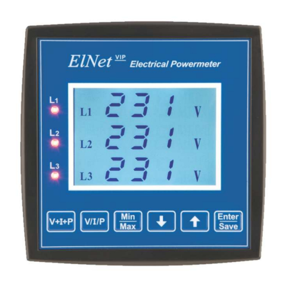
Measured values display 5.1 Use the "↑ ↓" buttons to browse among all the display screens including three-phase display of voltage, current, power, frequency, power factor and integrated screens of voltage, current and power factor for each phase. Peaks display 6.1 Pressing the Hi/Lo button (each press replaces screens circularly), enables you to browse among the screens specifying the peak of voltage and... -
Page 10: Indication Led
Indication led indication easily enables identify whether there is voltage in phases L1, L2, L3. In case there is voltage in phases connections the led will be turned on (50 VAC at least). -
Page 11: Communication Settings (For Devices With Communication Port)
8.2 Baud Rate: The Baud Rate is the communication speed in Bits per second (BPS) for communication between ElNet VIP with the PC or other device. The better the communication line quality, the faster the communications may be (higher Baud Rate value). - Page 12 The parity can be defined as ODD, NONE or EVEN. 8.5 Set up Communication 8.5.1 Press the "Enter" button for about 6 seconds until the insert password screen will appear. 8.5.2 Use the "↑" to change the password (COD) to "2" and press "Enter". 8.5.3 The message "SET"...
- Page 13 8.5.4 Use the "↑ ↓" buttons to chose the required communication feature and press "Enter": • Address "Adr" – can be changed by using "↑ ↓" buttons from 1 to 255, when finished press "Enter". • Baud "bud" – use the "↑ ↓" buttons to choose 300,600,1200,2400,4800,9600,19200.
-
Page 14: No Volt Relay
No volt relay 9.1 General: When the voltage is proper (above 50VAC, adjustable) and the phases' order is proper the indication relay is closed, as appears at the wiring diagram. The maximum current that is possible to transfer through this relay is 150ma which is enough to operate a regular control relay. - Page 15 9.2 Phase order alarm: 9.3.1 In order to turn ON/OFF the phase order relay, press the "Enter" button for about 6 seconds. 9.3.2 Use the "↑ ↓" buttons to "code 31" and press Enter. 9.3.3 The phase order screen will appear and it would enable you to select YES/NO (equivalent to ON/OFF).
Need help?
Do you have a question about the VIP and is the answer not in the manual?
Questions and answers