
Related Manuals for ELNet LT


Summary of Contents for ELNet LT
- Page 1 Installation & Operation Manual ELNet LT Electrical Measurements & Power Quality Rev. 1.9...
-
Page 2: Table Of Contents
Table of Contents CHAPTER 1 ─ INTRODUCTION ........5 1.1 — About the ELNet LT Energy Powermeter ..5 1.2 — How to use this manual ......... 6 1.3 — Safety Information ..........7 1.4 — Warranty ..............8 1.5 — Your comments are welcome .......10 1.6 —... - Page 3 CHAPTER 5 — FRONT PANEL DISPLAYS ....47 5.1 — Current Voltage & Frequency ......47 5.2 — Reset I , V , F Peak values ........49 5.3 — Power Display ............51 5.3.1 — Real time power display ........ 51 5.3.2 —Reset power peak values ......... 53 5.3.3 —...
- Page 4 6.2 — Registers for ELNet LT Powermeter ....67 6.2.1 — Registers addresess ........68 6.3 — Communication Connections ......69 6.4 — Communication Settings ........69 6.4.1 — Communication Address ....... 70 6.4.2 — Baud Rate ............70 6.4.3 — Parity............... 70 6.5 —...
-
Page 5: Chapter 1 ─ Introduction
CHAPTER 1 ─ INTRODUCTION 1.1 — About the ELNet LT Energy Powermeter Large consumers of electricity e.g. factories, hotels, hospitals, municipalities, need to know the history of their consumption and the quality and the values of the power supply. Details such... -
Page 6: How To Use This Manual
ELNet LT CHAPTER 1, Introduction, describes the Energy & Powermeter its potential users, the readings it can provide and some of its features in brief. -
Page 7: Safety Information
CHAPTER 6, Communications provides details about the Communication capabilities of the ELNet LT Energy & Powermeter , and how to Set Up. CHAPTER 7, Specifications, is a detailed list of specifications of the ELNet LT Energy & Powermeter APPENDIX A, Installation & Configuration Check List, provides a Check List to insure no important steps will be missed during the initial set up. -
Page 8: Warranty
CONTROL APPLICATIONS Ltd does not accept liability for any damage that may be caused by natural disasters (such as floods, fire, earthquake, lightening etc.). CONTROL APPLICATIONS Ltd does not accept liability for any damage that may be caused by malfunction of the ELNet Energy & Powermeter. - Page 9 CONTROL APPLICATIONS Ltd will advise the customer on the proper installation and use of the ELNet LT Energy & , but will not accept any responsibility that the Powermeter instrument is suitable for the application for which it was originally purchased.
-
Page 10: Your Comments Are Welcome
1.5 — Your comments are welcome CONTROL APPLICATIONS Ltd. sincerely thanks you for . We are choosing our ELNet LT Energy & Powermeter confident that it will provide you with many years of trouble free service and give you all the power and energy information and history that you expected from the instrument when you bought it. -
Page 11: Disclaimer
1.6 — Disclaimer Information in this User Manual is subject to change without notice and does not represent a commitment on the part of CONTROL APPLICATIONS Ltd. CONTROL APPLICATIONS Ltd supplies this User Manual as is without warranty of any kind; either expressed or implied, and reserves the right to make improvements and/or changes in the manual or the product at any time. -
Page 12: Chapter 2 - Installation
Refer to Section 1.3 Safety information • before carrying out any installation. Read this manual thoroughly and make sure • you understand the contents before connecting the ELNet LT Energy & to any power source. Powermeter... -
Page 13: Contents Of Packaging
ELNet LT Energy & Power Powermeter To unpack the The ELNet LT Energy & Powermeter is packed and shipped in a carton approximately 24.5 cm long X 19 cm wide X 12 and cm high. Before opening the package, ensure the area, clean and dry. -
Page 14: Mechanical Mounting
2.2 — Mechanical mounting ELNet LT Energy & Powermeter To Mount the NOTE!! ELNet LT Energy & Powermeter too Do not mount the close to any main electrical conductors Allow sufficient space to carry out maintenance to the back of ELNet LT Energy &... - Page 15 (ensure it is the right way up), then push the four mounting clips into position. Use mild force to ensure the clips are securely positioned on the outer case of the ELNet LT Energy & Powermeter. ELNet Energy &...
-
Page 16: Wiring Schematics
2.3 — Wiring Schematics ELNet LT Energy & Powermeter To wire up the No galvanic connection with the measurement current wire (the current wire is passing through the current CT hole). Figure 2.3 Schematic Wiring Diagram "Star" connection... - Page 17 No galvanic connection with the current measurement wires, the current wires are passing through the current transformer opening. Figure 2.4 Schematic Wiring Diagram "Delta" connection...
- Page 18 No galvanic connection with the current measurement wires, the current wires are passing through the current transformer opening. Figure 2.5 Schematic Wiring Diagram "Open Delta - 2PTs 2CTs/3CTs" connection...
- Page 19 ELNet LT 2013 Energy & Powermeter New model The current measurement wires are connected with screws to build in standard connectors or optional 60 mm connectors. Figure 2.6 Schematic Wiring Diagram "Star" connection...
- Page 20 The current measurement wires are connected with screws to build in standard connectors or optional 60 mm connectors. Figure 2.7 Schematic Wiring Diagram "Delta" connection...
- Page 21 The current measurement wires are connected with screws to build in standard connectors or optional 60 mm connectors. Figure 2.8 Schematic Wiring Diagram "Open Delta - 2PTs 2CTs/3CTs" connection...
- Page 22 ELNet LTP Energy & Powermeter No galvanic connection with the measurement current wire (the current wire is passing through the current CT hole).
- Page 23 No galvanic connection with the measurement current wire (the current wire is passing through the current CT hole).
- Page 24 No galvanic connection with the measurement current wire (the current wire is passing through the current CT hole).
-
Page 25: Rear Panel Connections
2.4 — Rear Panel Connections Please re-read section 1.3 for safety instructions. To connect the Rear Panel All Connections, except those to the CT core of the ELNet LT Energy & Powermeter are made via terminal connector plugs (Voltage input, Power Supply, Communication etc.). - Page 26 WARNING Never allow an open circuit between the two Current Transformer leads. Repeat the procedure for Line 2 and Line 3. Connect the rest of the connections to the ELNet LT Energy & Powermeter by means of terminal connector plugs.
- Page 27 Figure 2.13 New Model Rear Panel Figure 2.14 LTP Model Rear Panel...
- Page 28 Description Remarks Designation Line1 Supplied Voltage Through a 6Amp fuse Line2 Supplied Voltage Through a 6Amp fuse Line3 Supplied Voltage Through a 6Amp fuse Neutral Measurement neutral Line Description Remarks Designation From Current Note the correct direction to Transformer on Line1 insert the lead.
- Page 29 RS485 - RS485 Comm. (-) Line RS485 + RS485 Comm. (+) Line Digital Out Dry contact between Max. Load 150 mA pin 4 and 5 Digital Digital inputs 6 and 7 On = 220VAC Input for monitoring Table 2.1 Rear Panel connections...
-
Page 30: Digital Outputs And Inputs
5, the maximum load is 150mA. Digital Inputs: In order to change the status of the Digital Inputs of the LT a 220 VAC contact must be provided. The indication voltage should be supplied from one of the measured phases. The digital inputs can be monitored by communication and appear at the communication list. -
Page 31: Manufacturing Data
2.6 — Manufacturing Data. Press F1 on the keyboard for 6 seconds. The following screen will appear. Figure 2.16 Manufacturing data Number Screen Description Ep. Date Production date of software operating system Version Bios Revision CT Rate Current transformer ratio Type Hardware type and electrical network connection Unit ID... -
Page 32: Chapter 3 - Using Elnet Lt Powermeter
CHAPTER 3 — USING ELNet LT POWERMETER In this chapter you will find descriptions and functions of the front panel and the control buttons and how to use them. 3.1 — Front Panel To operate the front panel The Front Panel has a graphic screen and 6 operating buttons. -
Page 33: Control Buttons
3.2 — Control Buttons To operate the Control Buttons on Front Panel ELNet LT Energy & Powermeter has six Control Buttons. With these buttons the User Senior Electrical can achieve all the functions necessary. Engineer The Control Buttons are arranged on a keypad below the display screen and require slight finger pressure to click. -
Page 34: Lock Utility
(6) seconds. “ENTER” A “Keyboard Unlocked!” message appears on the screen and normal functions can resume. ELNet LT Energy In the event of a general power failure, the & Powermeter will return to the screen that was showing before... -
Page 35: Chapter 4 - Necessary Elnet Lt Settings
CHAPTER 4 — NECESSARY ELNet LT SETTINGS In this chapter you will find instructions to set the minimum settings that are necessary to allow the ELNet LT Energy & Powermeter to function properly. WARNING! The selection, installation and settings of the •... - Page 36 4.0 — Entering code The most important setting necessary for the proper ELNet LT Energy & functioning Powermeter is the Current Transformer setting. The cross section of the leads to the current Transformer must be compatible to the power of the current transformer.
-
Page 37: Settings For Current/Voltage Transformer
3 Use the buttons F3 & F4 to move the cursor, to set the value use buttons F1 &F2. 4 Click “ENTER” If the incorrect password is inserted into the Password field, an Error message appears and the password should be reentered The Technical Menu screen appears Figure 4.2 Technical Menu Use the buttons F3 &... -
Page 38: Electrical Connection Check
1 Scroll to Transformers ratio and select current or voltage transformer ratio to be set. 2 Click “ENTER”. The Current / Voltage Transformer screen appears Figure 4.3 Current Transformer The present setting for the Current Transformer is shown. Use the buttons F3 & F4 to move the cursor, to set the ratio use buttons F1 &F2. - Page 39 The proper current direction connection ("K" and "L") between the External CT and the ELNet is very important in case that the energy direction is monitored and the energy should be logged as Import (consumed) or Export (produced) modes. ELNet energy powermeter can auto correct the wrong current direction wiring (in case the Export energy is not required to be logged).
- Page 40 To perform Electrical connection Check 1 From Main Menu scroll to Technical. 2 Click The Enter Code screen appears. “ENTER”. 3 Enter code: 11 The Connections Test screen appears Figure 4.5 Connections Test Very important – very common problem!!!!! The information above and under is accurate only if there is a phase coloration between the current and voltage.
- Page 41 Table 4.1 Voltage and Current Messages Message Voltage Current Voltage “OK” present on Lines. Current present in If “OK” is not present on 3 Lines and synchronized Lines, then it is not connected with Voltage Lines. If correctly “OK” is not present on 3 Lines, then it is not connected correctly Wired in incorrect...
-
Page 42: Change Language
4.3 — Change language To change language on the display screen See Section 4.0 for instructions to arrive at the Technical Menu From Technical Menu scroll to "NEXT" and "LANGUAGE". 1 Click “ENTER” The Set Language screen appears Figure 4.6 Set Language 4.4 —... -
Page 43: Date Settings
2. Use the buttons F3 & F4 to move the cursor, to set the value use buttons F1 & F2. 4.5 — Date Settings To set Date See Section 4.0 for instructions to arrive at the Technical Menu. From Technical Menu scroll to Set Date 1 Click “ENTER”... -
Page 44: Setting Energy Pulse Out
4.6 — Setting energy pulse out The digital output (chapter 2.5) can be used as a pulse output, each pulse equivalent to pre define energy consumption value, in order to set the pulse output - See Section 4.0 for instructions to arrive at the Technical Menu. -
Page 45: Delta/Star Electrical Network Definition
4.7 — Delta/Open Delta/Star Electrical network definition The ELNet LT can be installed in three types of electrical networks: DELTA – a system without neutral line. Open Delta (Aron) – a system without neutral line. - Page 46 In order to change the type of the electrical network connected to the ELNet LT See Section 4.0 for instructions to arrive at the Technical Menu. 1 From Technical Menu scroll to "Next" then to "Wiring” and Click “ENTER”. 2 Scroll to “Delta/Star System”.
-
Page 47: Chapter 5 - Front Panel Displays
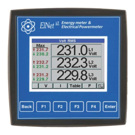
CHAPTER 5 — FRONT PANEL DISPLAYS In this chapter you will find instructions on how to obtain the readings that the ELNet LT Energy & Powermeter provides, e.g., Current, Voltage Power, Power Factor, Energy, and Power quality. 5.1 — Current Voltage & Frequency To display Current Voltage and Frequency for all 3 Phases 1 From Main Menu scroll to Voltage, Current, Hz. - Page 48 3 Scroll to REAL TIME DISPLAY and click “ENTER” The Current Voltage and Frequency screen appears Figure 5.3 Voltage screen 4 Use “F1” in order to display voltage values. 5 Use “F2” in order to display current values. 6 Use “F3” in order to display Current and Voltage table view.
-
Page 49: Reset I , V , F Peak Values
Measuring the leakage current provides a very important safety indication. If the leakage current exceeds the required safety standards level a special and urgent examination of the electrical system is required. ELNet LTP Energy & Powermeter measures the leakage current by using the existing standard measurement current transformers. - Page 50 To display the Leakage Current. From Main Menu scroll to Voltage, Current, Hz. Click “ENTER”. The Current Voltage and Frequency screen appears. Scroll to Leakage Current and click “ENTER” The Leakage Current screen appears In order to set the Allowed Leakage level, click on the F1 button.
-
Page 51: Power Display
Use the buttons F3 & F4 to move the cursor, to set the value use buttons F1 &F2. 5.4 — Power Display 5.4.1 — Real time power display To display Power for all 3 phases 1 From Main Menu scroll to Power, power factor Display. 2 Click “ENTER”. - Page 52 The Power, Power factor screen appears Figure 5.7 Power, Power factor 3 Scroll to REAL TIME DISPLAY and click “ENTER”. The real time Power, Power factor screen appears Figure 5.6 Power factor 4 Use “F1” in order to display Reactive Power values. 5 Use “F2”...
-
Page 53: Reset Power Peak Values
Parameter Description Unit Active Power for each Line Watts Reactive Power for each Line Apparent Power for each Line Σ P Total Active Power for all 3 Lines Watts Σ Q Total Reactive Power for all 3 Lines Σ S Total Apparent Power for all 3 Lines Power Factor Table 5.1 Power Readings... -
Page 54: Power Quality
NOTE! Poor Harmonics could invoke a fine and damage to the electrical system and can be improved by adding filters. The ELNet LT Energy & Powermeter is capable of displaying Harmonics in Wave Form Graph, Harmonics Bar Graph, for Voltage and Current. -
Page 55: Wave Form Display
5.5.1 — Wave Form Display To display Wave Form Graphs 1 From Main Menu scroll to Power Quality. 2 Click “ENTER” The Power Quality screen appears Figure 5.8 Power Quality 3 Scroll to Waveform Display and click “ENTER”. The Wave form Graphs screen appears Figure 5.11 Voltage Graph... -
Page 56: Harmonics Analyzer & Thd
NOTE! Available Waveform Graphs Volts Line 1, Line 2 and Line 3 Current Line 1, Line 2 and Line 3 Use “F1” in order to display voltage waveform. Use “F2” in order to display current waveform Use “F4” in order to toggle between L1, L2, L3. 5.4.2 —... -
Page 57: Alarm Setup
Use “F1” “F2” in order to toggle the display between current waveform and voltage waveform. Use “F3” in order to toggle between L1, L2, L3 and All together. Use “F4” in order to display and toggle between the harmonics values up to the 64 harmony. -
Page 58: Energy Metering
Scroll to Alarm setup and click “ENTER”. The Alarm setup screens appear, and you will be requested to select the electrical measurement to be defined (voltage/ current / demand / KW IMP. / KW EXP) by pressing, “Enter” and set the alarm levels. 5.6 —... -
Page 59: Main Energy Meter
By using the sub menu you will be able to: By using “F1” The ELNet will display the amount of the energy used for each rate: RT1 = Rate number 1... -
Page 60: 2Nd. Energy Meter
The accumulated energy data in this meter can be erasable (“cleared”) by the user. By using the sub menu you will be able to: By using “F1” The ELNet will display the amount of the energy used for each rate: RT1 = Rate number 1... -
Page 61: T.o.u Energy
5.5.3 — T.O.U Energy ELNet LT Energy & Powermeter record all energy values according to the T.O.U (time of use) schedule. Each country has different T.O.U (time of use) schedule , in order to select the T.O.U schedule See Section 4.0 for instructions to arrive at the Technical Menu 1 From Technical Menu scroll twice to NEXT. -
Page 62: Periodic Energy Meter
By using “F1” (DATE) the user can define two dates in order to set the period of time for calculating the active energy in this period: By Using “F2” The ELNet will display the amount of the active energy used for each rate:... -
Page 63: Chapter 6 - Communication
6.1.1— RTU Transmission Mode MODBUS uses the standard Remote Terminal Unit (RTU) transmission mode. RTU mode sends data in 8-bit binary EVEN parity or 8-bit binary NO parity data format. For the ELNet LT Energy & Powermeter to successfully communicate, choose one in... -
Page 64: The Rtu Frame Format
Field No. of bits Start bit Data bits Parity Stop it Table 6.1 RTU Data Format 6.1.2 — The RTU Frame Format Query and response information is sent in frames. Each frame contains: Address Function (See Section 6.1.4 for descriptions of functions), Data Check Address Function... -
Page 65: Address Field
247. The Powermeter will only respond to its own specifically assigned address. 6.1.4 — Function Field The function field contains the code that tells the Powermeter what action to perform. ELNet LT Energy & Powermeter uses and responds to four standard Message Format Functions. Function 03... -
Page 66: Data Field
6.1.5 — Data Field The Data field contains the body of the message and contains instructions from the PC master to the Powermeter slave to perform a particular action or respond to a query. The reply message from the Powermeter will be information contained in one or more of its registers. -
Page 67: Registers For Elnet Lt Powermeter
The difference is significant because by using Function 03 the ELNet LT will only send the INTERGER part of the field value requested and the PC master will only display the INTERGER part of the field value. -
Page 68: Registers Addresess
1 and 2 giving the full FLOAT value (in IEEE Format) from that field i.e. 230.5V. 6.2.1 — Registers addresess ELNet LT MODBUS registers addresses are updated all the time and can be downloaded from the following web site: http://www.ddc.co.il/ELNet-pdf/ELNet_comm.pdf... -
Page 69: Communication Connections
Connections are provided on the Rear Panel, (Please refer to section 2.3) and are made by means of the connectors provided. 6.4 — Communication Settings To enable the User to connect the ELNet LT Energy & Powermeter to a PC computer for successful communications, the Communication Setup parameters of both must match;... -
Page 70: Communication Address
MODBUS, the available addresses are - from ‘1’ to ‘247’ 6.4.2 — Baud Rate The Baud Rate is the communication speed in Bits per second (BPS) that the ELNet LT Energy & Powermeter communicates with the PC. The better the communication line Quality, the faster the communications may be. -
Page 71: Communication Set Up
6.5 — Communication Set Up 6.5.1 — Set up Serial Communications See Section 4.1 for instructions to reach the Technical Menu. 1 From Technical Menu scroll to Set Communication. 2 Click “ENTER” 3 Scroll to "Serial Comm." and click "Enter". The Serial Communication Setup screen appears Figure 6.2 Serial Communication Setup Use buttons F1 &F2, to set the values... -
Page 72: Set Up Ethernet Communications
6.5.2 — Set up Ethernet Communications See Section 4.1 for instructions to reach the Technical Menu. 1 From Technical Menu scroll to Set Communication. 2 Click “ENTER” 3 Scroll to "Ethernet" and click "Enter". The Ethernet Communication Setup screen appears Figure 6.3 Ethernet Communication Setup 4 Scroll to "Set IP"... -
Page 73: Communication With Uniart Software
1-4. 6.6 — Communication with UniArt Software CONTROL APPLICATIONS Ltd propriety software, “UniArt” is used to Read and Write Registers of the ELNet LT Energy Powermeter. Each Item number in the Registers Table is a unique field containing information. - Page 74 4 Go to the correct Point number within that file Point number is determined by the formula: Item number – [FILE X 128] = Point Number E.G. 1 If the user the wishes to read Voltage Line 2 (Item No 2) By applying the formula: 2 - [0 X 128] = 2 File = 0 and Point within that file = 2 E.G.
-
Page 75: Chapter 7 - Specifications
CHAPTER 7 — Specifications Item Description Power requirements 85-260V AC or 110-300V DC ,60/50 Hz, 5VA Dimensions (HxWxD) 960x960x80 mm Shipping Weight 620 gr. Measuring voltage limits 700VAC Measuring current limits Operating Voltage limits 1000 V Operating Current limits 50 A Enclosure material ABS + Anti flame Display... -
Page 76: Measurement & Display
7.1 — Measurement & Display Measurement & Display (scaling factor 1) Measurement Display Range Measuring in Display Range Parameter direct in direct connection connection (scaling factor 1) (scaling factor 1) 0.001 – 6A 0.001 – 6A 0.001 – 99999KA Current 0.001 –... - Page 77 Measurement & Display (scaling factor 1) Measurement Display Range Measuring in Display Range Parameter direct in direct connection connection (scaling factor 1) (scaling factor 1) 0.000 – 100% Harmonic THD 0.000 – 100% Partial Harmonic V\I Operating hour 99999-HH:MM:SS meter Table 7.2 Measurement &...
-
Page 78: Index
Index Appendix A — Installation & Configuration Check List INSTALLATION CHECK LIST Description Date Signature Check contents of packaging Remove from packaging Prepare hole Mount Powermeter Connect Powermeter power supply Connect 3 Current Transformers Connect 3 Voltage lines Connect Neutral line Set Current Transformer Ratio Connect Communication lines Check Phase Order Connections...
Need help?
Do you have a question about the LT and is the answer not in the manual?
Questions and answers