Moeller PKZM0 Hardware And Engineering
Motor-protective circuit-breaker pkzm0 overload monitoring of eex e motors
Hide thumbs
Also See for PKZM0:
- Installation instructions (3 pages) ,
- Installation instructions (3 pages)
Table of Contents
Advertisement
Available languages
Available languages
Quick Links
Advertisement
Chapters
Table of Contents

Related Manuals for Moeller PKZM0


Summary of Contents for Moeller PKZM0
- Page 1 Motorschutzschalter PKZM0 Überlastüberwachung von EEx e-Motoren Motor-protective circuit-breaker PKZM0 Overload monitoring of EEx e motors Hardware und Projektierung Hardware and Engineering 04/06 AWB1210-1458D/GB T hink future. Switch to green.
- Page 2 No part of this manual may be reproduced in any form (printed, photocopy, microfilm or any otherprocess) or processed, duplicated or distributed by means of electronic systems without written permission of Moeller GmbH, Bonn. Subject to alterations without notice. Printed on bleached cellulose.
- Page 3 Warnung! Warning! Gefährliche Dangerous elektrische electrical Spannung! voltage! Vor Beginn der Installationsarbeiten Before commencing the installation • Gerät spannungsfrei schalten. • Disconnect the power supply of the device. • Gegen Wiedereinschalten sichern. • Ensure relosing interlock that devices cannot be accidentally restarted. •...
- Page 4 04/06 AWB1210-1458D/GB Überblick/Overview Motorschutzschalter PKZM0 Überlastüberwachung von EEx e-Motoren PKZM0 motor-protective circuit-breaker Overload monitoring of EEx e motors Anhang/Appendix...
-
Page 5: Table Of Contents
Zu diesem Handbuch Zielgruppe Abkürzungen und Symbole Änderungsprotokoll Motorschutzschalter PKZM0 Vorwort Geräteübersicht Gerätebeschreibung – Überlastschutz mit Motorschutzschaltern – Strombereiche der Motorschutzschalter PKZM0 – Temperaturkompensation – Phasenausfall – Wiedereinschaltung – Testfunktion Projektierung Überlastüberwachung von EEx e-Motoren Einstellung der Überstromschutzeinrichtung Kurzschluss-Schutz der Motorschutzschalter... -
Page 6: Inhalt
04/06 AWB1210-1458D/GB Inhalt Anhang/Appendix Typenschild/Rating plate PKZM0 Auslösekennlinien/Tripping characteristics PKZM0 39 – PKZM0-0,16 – PKZM0-0,25 – PKZM0-0,4 – PKZM0-0,63 – PZKM0-1 – PKZM0-1,6 – PKZM0-2,5 – PKZM0-4 – PKZM0-6,3 – PKZM0-10 – PKZM0-12 – PKZM0-16 – PKZM0-20 – PKZM0-25 – PKZM0-32... -
Page 7: Zu Diesem Handbuch
04/06 AWB1210-1458D/GB Zu diesem Handbuch Das vorliegende Handbuch gilt für Motorschutzschalter PKZM0. Dieses Handbuch beschreibt die Überlastüberwachung zum Schutz von Motoren in explosiongefährdeten Bereichen (EEx e-Bereichen). Zielgruppe Dieses Handbuch richtet sich an Fachpersonal, das den Motorschutzschalter installiert, in Betrieb nimmt und wartet. -
Page 8: Änderungsprotokoll
Auslösekennlinie „Abbildung 24: PKZMO-32“ „Konformitätserklärung/Declaration of Conformity“ 04/04 „Strombereiche der Motorschutz- schalter PKZM0“ Tabelle 2: „Schaltvermögen PKZM0 mit Zuordnungsart „1“ und „2““ „Zulassungen“ Tabelle 4: „Leistungsdaten Nordame- rika der einzelnen Typen“ Tabelle 5 „Weitere Leistungsdaten der einzelnen Typen“ Typ „PKZM0-12“... -
Page 9: Motorschutzschalter Pkzm0
Die Richtlinie 94/9/EG (ATEX 100a) zur Angleichung der Rechtsvorschriften der Mitgliedsstaaten für Geräte und Schutzsysteme zur bestimmungsmäßigen Verwendung in explosionsgefährdeten Bereichen wird ab dem 30.06.2003 bindend. Das Motorschutzsystem PKZM0 ist nach der Richtlinie 94/9/EG (ATEX 100a) durch die PTB zugelassen. Die EG-Baumusterprüfbescheinigungs-Nummer lautet: PTB 02 ATEX 3151. -
Page 10: Geräteübersicht
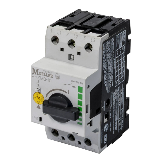
Überlastschutz mit Motorschutzschaltern Die Motorschutzschalter PKZM0 sind dreipolige elektro- mechanische Motorschutzschalter mit Bimetallen zur Über- lastüberwachung Bei einer Überlastauslösung schaltet der PKZM0 allpolig den Hauptstromkreis ab. Somit wird der Stromfluss des zu über- wachenden Motors direkt abgeschaltet. L1 L2 L3 I >... -
Page 11: Strombereiche Der Motorschutzschalter Pkzm0
04/06 AWB1210-1458D/GB Gerätebeschreibung Strombereiche der Motorschutzschalter PKZM0 Die PKZM0 werden mit Hilfe einer Stromeinstellscheibe a (a Abb. 1 auf Seite 6) auf den Motornennstrom einge- stellt. Mit 15 verschiedenen Typen können Motoren von 0,1 bis 32 A Motornennstrom überwacht werden (a Tabelle 1). -
Page 12: Phasenausfall
Abbildung 3: Funktion der Phasenausfallempfindlichkeit mit Hilfe einer Auslöse- und Differenzialbrücke a Auslösebrücke b Differenzialbrücke c Abstand d Differenzweg Soll mit dem PKZM0 ein Wechselstrommotor oder ein Gleichstrommotor überwacht werden, muss der Strom über alle drei Strombahnen geführt werden, um Früh- auslösungen zu vermeiden. -
Page 13: Wiedereinschaltung
Wiedereinschaltung Nach einer Auslösung müssen zunächst die Bimetalle abkühlen, bevor der Motorschutzschalter wieder eingeschaltet werden kann. Beim Motorschutzschalter PKZM0 ist nur eine manuelle Wiedereinschaltung vor Ort möglich. Testfunktion Durch eine zusätzliche Testeinrichtung b (a Abb. 1 auf Seite 6) kann die Funktionstüchtigkeit des Schalters kontrol- liert werden. - Page 14 04/06 AWB1210-1458D/GB...
-
Page 15: Projektierung
04/06 AWB1210-1458D/GB Projektierung Überlastüberwachung von Durch besondere konstruktive Maßnahmen erreicht man bei EEx e-Motoren Motoren die Zündschutzart EEx e. Die Motoren werden auf Basis der höchst zulässigen Oberflächentemperaturen Temperaturklassen zugeordnet. Zusätzlich wird die Erwär- mungszeit t und das Verhältnis Anlaufstrom zu Nennstrom bestimmt und auf dem Motor angegeben. -
Page 16: Kurzschluss-Schutz Der Motorschutzschalter
= 6, t = 10 s Abbildung 5: Auslösekennlinie des Motorschutzschalters Der Motor wird zuverlässig geschützt. Kurzschluss-Schutz der Die folgende Tabelle 2 zeigt das Kurzschlussausschaltver- Motorschutzschalter mögen der Motorschutzschalter PKZM0. Zur Erhöhung des Schaltvermögens auf 100 kA können Sicherungen vorgeschaltet werden. - Page 17 04/06 AWB1210-1458D/GB Kurzschluss-Schutz der Motor- schutzschalter Tabelle 2: Schaltvermögen PKZM0 mit Zuordnungsart „1“ und „2“ 230 V 400 V 440 V 500 V 690 V [kA] [kA] [kA] [kA] [kA] 0,16 – 1 Kein vorgeschaltetes Schutzorgan notwendig, da eigenfester Bereich (100/150 kA)
-
Page 18: Zulassungen
04/06 AWB1210-1458D/GB Projektierung Zulassungen Der Motorschutzschalter PKZM0 ist nach der Vorschrift IEC EN 60947 Niederspannungsschaltgeräte gebaut und erfüllt die Forderungen nach der Richtlinie 94/9/EG (ATEX 100a) zum Schutz von EEx e-Motoren. Außerdem können nach EN 50281-1-1 und EN 50281-1-2 Motoren in den Zonen 21 und 22 (Bereiche mit brennbarem Staub) geschützt werden. -
Page 19: Installation
Montageanweisung AWA1210-1925 auf der Innenseite der Kartonverpackung zu beachten. Warnung! Rücksetzungen dürfen manuell vor Ort oder durch geschultes Personal in der Leitwarte vorgenommen werden. Geräte montieren Abbildung 6: Montage PKZM0 Montieren Sie den Motorschutzschalter nur wie in Abb. 7 dargestellt. - Page 20 04/06 AWB1210-1458D/GB Installation Abbildung 7: Zugelassene Einbaulagen für Motorschutzschalter PKZM0 Verdrahten Sie die Motorleitungen. > > > > > > Abbildung 8: Hauptstromverdrahtung Folgende maximale Leitungsquerschnitte sind möglich. Tabelle 3: Maximale Leitungsquerschnitte der Motorzuleitungen 1 bis 6 mm 1,7 Nm...
-
Page 21: Geräte Betreiben
Einstellungen Vor der Erstinbetriebnahme des Motorschutzschalters muss der Motornennstrom mit Hilfe der Stromeinstellscheibe a am PKZM0 eingestellt werden (a Tabelle 1 auf Seite 7). Test Der Motorschutzschalter verfügt über eine Testeinrichtung b (a Abbildung 1 auf Seite 6). Wird diese Testeinrichtung bei eingeschaltetem Motorschutzschalter mittels eines Schraubendrehers betätigt, löst der PKZM0 aus und alle... - Page 22 04/06 AWB1210-1458D/GB...
- Page 23 PKZM0 motor-protective circuit-breakers Preface Overview of the devices Unit description – Overload protection with motor-protective circuit- breakers 24 – Current ranges of the PKZM0 motor-protective cir- cuit-breaker 25 – Temperature compensation – Phase failure – Reset – Test function Configuration...
- Page 24 04/06 AWB1210-1458D/GB Contents Anhang/Appendix Typenschild/Rating plate PKZM0 Auslösekennlinien/Tripping characteristics PKZM0 39 – PKZM0-0,16 – PKZM0-0,25 – PKZM0-0,4 – PKZM0-0,63 – PZKM0-1 – PKZM0-1,6 – PKZM0-2,5 – PKZM0-4 – PKZM0-6,3 – PKZM0-10 – PKZM0-12 – PKZM0-16 – PKZM0-20 – PKZM0-25 – PKZM0-32...
-
Page 25: About This Manual
04/06 AWB1210-1458D/GB About this manual This manual applies to the PKZM0 motor-protective circuit- breakers. It describes the overload monitoring system for the protection of motors operating in potentially explosive atmospheres (EEx e areas). Target group This manual addresses skilled personnel who install, commission and service the motor-protective circuit- breakers. -
Page 26: List Of Revisions
Table “PKZM0-32” Tripping characteristic “Figure24: PKZMO-32” “Konformitätserklärung/Declaration of Conformity” 04/04 “Current ranges of the PKZM0 motor- protective circuit-breaker” Table 2: “Switching capacity of PKZM0 with protection type "1" and "2"” “Approvals” Table 4: “Rating data of the individual types for North America”... -
Page 27: Pkzm0 Motor-Protective Circuit-Breakers
Member States concerning equipment and protective systems intended for use in potentially explosive atmospheres will be enforced as of 06.30.2003. The motor-protective PKZM0 system is approved by the PTB according the 94/9/EC (ATEX 100a) Directives. Number of the EU Certificate of Compliance:... -
Page 28: Overview Of The Devices
The PKZM0 series are 3-phase electromechanical motor- protective circuit-breakers with bimetallic release for overload monitoring. The PKZM0 disconnects all phases from the mains circuit when an overload occurs. The current flow to the monitored motor is thus switched off directly. -
Page 29: Current Ranges Of The Pkzm0 Motor-Protective Circuit-Breaker
Unit description Current ranges of the PKZM0 motor-protective circuit-breaker The rated motor current is set on the PKZM0 units by means of a current dial a (a Fig. 1, Page 24). 15 different types are available for monitoring motors with a rated current from 0.1 to 32 A (a Table 1). -
Page 30: Phase Failure
Tripping bridge b Differential bridge c Gap d Differential distance When a PKZM0 is to be used for monitoring an AC or DC motor, the current must flow across all three current paths in order to avoid early tripping. -
Page 31: Reset
Proper functioning of the circuit-breaker can be verified by means of the testing feature b (a Fig. 1, Page 24). The active PKZM0 motor circuit-breaker is tripped by actuating the test release with the help of a screwdriver. This allows the user to verify the proper functioning of the motor... - Page 32 04/06 AWB1210-1458D/GB...
-
Page 33: Configuration
04/06 AWB1210-1458D/GB Configuration Overload monitoring of The motors are compliant to EEx e type of protection EEx e motors through special construction measures. The motors are assigned to temperature classes on the basis of the highest permissible surface temperatures. The temperature rise time and the ratio between startup current and rated current are calculated in addition and specified on the rating plate of the motor. -
Page 34: Short-Circuit Protection Of The Motor-Protective Circuit-Breaker
The motor is reliably protected. Short-circuit protection of The following Table 2 shows the short-circuit breaking the motor-protective capacity of the PKZM0 motor circuit-breaker. circuit-breaker Fuse can be interconnected in the upstream circuit to increase the switching capacity to 100 kA. - Page 35 04/06 AWB1210-1458D/GB Short-circuit protection of the motor-protective circuit- breaker Table 2: Switching capacity of PKZM0 with protection type "1" and "2" 230 V 400 V 440 V 500 V 690 V [kA] [kA] [kA] [kA] [kA] 0,16 – 1 No upstream protective device required,...
-
Page 36: Approvals
04/06 AWB1210-1458D/GB Configuration Approvals The PKZM0 motor-protective circuit-breaker is compliant with IEC/EN 60947 regulations for low-voltage switchgear and fulfils the requirements of the 94/9/EC (ATEX 100a) directives for the protection of EEx e motors. Furthermore, motors in zones 21 and 22 (zones with combustible dusts) can be protected conform to EN 50281-1-1 and EN 50281-1-2. -
Page 37: Installation
AWA1210-1925 on the inside of the cardboard package must be observed. Warning! A manual reset may be carried out locally by trained personnel or in the control room. Mounting the devices Figure 6: Mounting the PKZM0 Always mount the motor circuit-breaker as shown in Fig. 7. - Page 38 04/06 AWB1210-1458D/GB Installation Figure 7: Approved mounting positions of the PKZM0 motor circuit-breaker Wire the motor cables > > > > > > Figure 8: Mains wiring The following conductor cross-sections can be used. Table 3: Maximum conductor cross-sections of the motor cables 1 to 6 mm 1.7 Nm...
-
Page 39: Operating The Devices
The motor-protective circuit-breaker is equipped with a testing feature b (a Figure 1, Page 24). The active PKZM0 motor-protective circuit-breaker is tripped by actuating the test release with the help of a screwdriver. This opens all power contacts and thus removes the output lines from the voltage source. - Page 40 04/06 AWB1210-1458D/GB...
-
Page 41: Anhang/Appendix
– 600 V AC IEC/EN 60947 kA – WHEN PROTECTED BY ANY OF THE FOLLOWING: II(2)GD –LISTED MOELLER CIRCUIT BREAKER NZM(H)6(b) –LISTED CURRENT LIMITING CIRCUIT BREAKER PER UL 489 –LISTED FUSE PTB 02 ATEX 3151 COMB.MTR. RATED AS SHOWN IN TABLE AND HAVING... - Page 42 04/06 AWB1210-1458D/GB Anhang/Appendix Tabelle/Table 4: Leistungsdaten Nordamerika der einzelnen Typen/ Rating data of the various types for North America Type PK(Z)M0-0,16(-T) – – – PK(Z)M0-0,25(-T) PK(Z)M0-0,4(-T) PK(Z)M0-0,63(-T) PK(Z)M0-1,0(-T) PK(Z)M0-1,6(-T) A/aj PK(Z)M0-2,5(-T) – PK(Z)M0-4,0(-T) PK(Z)M0-6,3(-T) PK(Z)M0-10(-T) PK(Z)M0-12(-T) – – – PK(Z)M0-16(-T) PK(Z)M0-20(-T) PK(Z)M0-25(-T) PK(Z)M0-32...
-
Page 43: Auslösekennlinien/Tripping Characteristics Pkzm0
04/06 AWB1210-1458D/GB Auslösekennlinien/Tripping characteristics PKZM0 Tabelle/Table 5: Weitere Leistungsdaten der einzelnen Typen/ Further rating data of the individual types Type PK(Z)M0-0,16(-T) 0.16 PK(Z)M0-0,25(-T) 0.25 PK(Z)M0-0,4(-T) PK(Z)M0-0,63(-T) 0.63 PK(Z)M0-1,0(-T) PK(Z)M0-1,6(-T) PK(Z)M0-2,5(-T) PK(Z)M0-4,0(-T) PK(Z)M0-6,3(-T) PK(Z)M0-10(-T) PK(Z)M0-12(-T) – – PK(Z)M0-16(-T) PK(Z)M0-20(-T) PK(Z)M0-25(-T) PK(Z)M0-32 Auslösekennlinien/... -
Page 44: Pkzm0-0,16
04/06 AWB1210-1458D/GB Anhang/Appendix PKZM0-0,16 Bereich/Range 0.1 – 0.16 A (NM – HM) Umgebungstemperatur/Ambient temperature 20 °C Auslöseklasse/Tripping class 10 A Toleranzbereich/Tolerance range g 20 % Einstellung/ Auslösezeit/Tripping time t [s] Setting 3-phase a 2-phase c 3-phase b 2-phase d 3 x I 11.8... - Page 45 04/06 AWB1210-1458D/GB Auslösekennlinien/Tripping characteristics PKZM0 6 7 8 9 10 Abbildung/Figure 10: PKZM0-0,16...
-
Page 46: Pkzm0-0,25
04/06 AWB1210-1458D/GB Anhang/Appendix PKZM0-0,25 Bereich/Range 0.16 – 0.25 A (NM – HM) Umgebungstemperatur/Ambient temperature 20 °C Auslöseklasse/Tripping class 10 A Toleranzbereich/Tolerance range g 20 % Einstellung/ Auslösezeit/Tripping time t [s] Setting 3-phase a 2-phase c 3-phase b 2-phase d 3 x I 20,5 19.7... - Page 47 04/06 AWB1210-1458D/GB Auslösekennlinien/Tripping characteristics PKZM0 6 7 8 9 10 Abbildung/Figure 11: PKZM0-0,25...
-
Page 48: Pkzm0-0,4
04/06 AWB1210-1458D/GB Anhang/Appendix PKZM0-0,4 Bereich/Range 0.25 – 0.4 A (NM – HM) Umgebungstemperatur/Ambient temperature 20 °C Auslöseklasse/Tripping class 10 A Toleranzbereich/Tolerance range g 20 % Einstellung/ Auslösezeit/Tripping time t [s] Setting 3-phase a 2-phase c 3-phase b 2-phase d 3 x I 12.5... - Page 49 04/06 AWB1210-1458D/GB Auslösekennlinien/Tripping characteristics PKZM0 6 7 8 9 10 Abbildung/Figure 12: PKZM0-0,4...
-
Page 50: Pkzm0-0,63
04/06 AWB1210-1458D/GB Anhang/Appendix PKZM0-0,63 Bereich/Range 0.4 – 0.63 A (NM – HM) Umgebungstemperatur/Ambient temperature 20 °C Auslöseklasse/Tripping class 10 A Toleranzbereich/Tolerance range g 20 % Einstellung/ Auslösezeit/Tripping time t [s] Setting 3-phase a 2-phase c 3-phase b 2-phase d 3 x I 22.5... - Page 51 04/06 AWB1210-1458D/GB Auslösekennlinien/Tripping characteristics PKZM0 6 7 8 9 10 Abbildung/Figure 13: PKZM0-0,63...
- Page 52 04/06 AWB1210-1458D/GB Anhang/Appendix PZKM0-1 Bereich/Range 0.63 – 1 A (NM – HM) Umgebungstemperatur/Ambient temperature 20 °C Auslöseklasse/Tripping class 10 A Toleranzbereich/Tolerance range g 20 % Einstellung/ Auslösezeit/Tripping time t [s] Setting 3-phase a 2-phase c 3-phase b 2-phase d 3 x I 26.5 17.5 7.2 x I...
- Page 53 04/06 AWB1210-1458D/GB Auslösekennlinien/Tripping characteristics PKZM0 6 7 8 9 10 Abbildung/Figure 14: PZKM0-1...
-
Page 54: Pkzm0-1,6
04/06 AWB1210-1458D/GB Anhang/Appendix PKZM0-1,6 Bereich/Range 1 – 1.6 A (NM – HM) Umgebungstemperatur/Ambient temperature 20 °C Auslöseklasse/Tripping class 10 A Toleranzbereich/Tolerance range g 20 % Einstellung/ Auslösezeit/Tripping time t [s] Setting 3-phase a 2-phase c 3-phase b 2-phase d 3 x I 17.7... - Page 55 04/06 AWB1210-1458D/GB Auslösekennlinien/Tripping characteristics PKZM0 6 7 8 9 10 Abbildung/Figure 15: PKZM0-1,6...
-
Page 56: Pkzm0-2,5
04/06 AWB1210-1458D/GB Anhang/Appendix PKZM0-2,5 Bereich/Range 1.6 – 2.5 A (NM – HM) Umgebungstemperatur/Ambient temperature 20 °C Auslöseklasse/Tripping class 10 A Toleranzbereich/Tolerance range g 20 % Einstellung/ Auslösezeit/Tripping time t [s] Setting 3-phase a 2-phase c 3-phase b 2-phase d 3 x I 21.5... - Page 57 04/06 AWB1210-1458D/GB Auslösekennlinien/Tripping characteristics PKZM0 6 7 8 9 10 Abbildung/Figure 16: PKZM0-2,5...
- Page 58 04/06 AWB1210-1458D/GB Anhang/Appendix PKZM0-4 Bereich/Range 2.5 – 4 A (NM – HM) Umgebungstemperatur/Ambient temperature 20 °C Auslöseklasse/Tripping class 10 A Toleranzbereich/Tolerance range g 20 % Einstellung/ Auslösezeit/Tripping time t [s] Setting 3-phase a 2-phase c 3-phase b 2-phase d 3 x I 22.1...
- Page 59 04/06 AWB1210-1458D/GB Auslösekennlinien/Tripping characteristics PKZM0 6 7 8 9 10 Abbildung/Figure 17: PKZM0-4...
-
Page 60: Pkzm0-6,3
04/06 AWB1210-1458D/GB Anhang/Appendix PKZM0-6,3 Bereich/Range 4 – 6.3 A (NM – HM) Umgebungstemperatur/Ambient temperature 20 °C Auslöseklasse/Tripping class 10 A Toleranzbereich/Tolerance range g 20 % Einstellung/ Auslösezeit/Tripping time t [s] Setting 3-phase a 2-phase c 3-phase b 2-phase d 3 x I 22.5... - Page 61 04/06 AWB1210-1458D/GB Auslösekennlinien/Tripping characteristics PKZM0 6 7 8 9 10 Abbildung/Figure 18: PKZM0-6,3...
- Page 62 04/06 AWB1210-1458D/GB Anhang/Appendix PKZM0-10 Bereich/Range 6.3 – 10 A (NM – HM) Umgebungstemperatur/Ambient temperature 20 °C Auslöseklasse/Tripping class 10 A Toleranzbereich/Tolerance range g 20 % Einstellung/ Auslösezeit/Tripping time t [s] Setting 3-phase a 2-phase c 3-phase b 2-phase d 3 x I 31.5...
- Page 63 04/06 AWB1210-1458D/GB Auslösekennlinien/Tripping characteristics PKZM0 6 7 8 9 10 Abbildung/Figure 19: PKZM0-10...
- Page 64 04/06 AWB1210-1458D/GB Anhang/Appendix PKZM0-12 Bereich/Range 8 – 12 A (NM – HM) Umgebungstemperatur/Ambient temperature 20 °C Auslöseklasse/Tripping class 10 A Toleranzbereich/Tolerance range g 20 % Einstellung/ Auslösezeit/Tripping time t [s] Setting 3-phase a 2-phase c 3-phase b 2-phase d 3 x I 27.3...
- Page 65 04/06 AWB1210-1458D/GB Auslösekennlinien/Tripping characteristics PKZM0 6 7 8 9 10 Abbildung/Figure 20: PKZM0-12...
- Page 66 04/06 AWB1210-1458D/GB Anhang/Appendix PKZM0-16 Bereich/Range 10 – 16 A (NM – HM) Umgebungstemperatur/Ambient temperature 20 °C Auslöseklasse/Tripping class 10 A Toleranzbereich/Tolerance range g 20 % Einstellung/ Auslösezeit/Tripping time t [s] Setting 3-phase a 2-phase c 3-phase b 2-phase d 3 x I 22.5...
- Page 67 04/06 AWB1210-1458D/GB Auslösekennlinien/Tripping characteristics PKZM0 6 7 8 9 10 Abbildung/Figure 21: PKZM0-16...
- Page 68 04/06 AWB1210-1458D/GB Anhang/Appendix PKZM0-20 Bereich/Range 16 – 20 A (NM – HM) Umgebungstemperatur/Ambient temperature 20 °C Auslöseklasse/Tripping class 10 A Toleranzbereich/Tolerance range g 20 % Einstellung/ Auslösezeit/Tripping time t [s] Setting 3-phase a 2-phase c 3-phase b 2-phase d 3 x I 25.5...
- Page 69 04/06 AWB1210-1458D/GB Auslösekennlinien/Tripping characteristics PKZM0 6 7 8 9 10 Abbildung/Figure 22: PKZM0-20...
- Page 70 04/06 AWB1210-1458D/GB Anhang/Appendix PKZM0-25 Bereich/Range 20 – 25 A (NM – HM) Umgebungstemperatur/Ambient temperature 20 °C Auslöseklasse/Tripping class 10 A Toleranzbereich/Tolerance range g 20 % Einstellung/ Auslösezeit/Tripping time t [s] Setting 3-phase a 2-phase c 3-phase b 2-phase d 3 x I 29.5...
- Page 71 04/06 AWB1210-1458D/GB Auslösekennlinien/Tripping characteristics PKZM0 6 7 8 9 10 x I r Abbildung/Figure 23: PKZM0-25...
- Page 72 04/06 AWB1210-1458D/GB Anhang/Appendix PKZM0-32 Bereich/Range 26 – 32 A offen/open (NM – HM) 26 – 30 A gekapselt/ encapsulated (NM – HM) Umgebungstemperatur/Ambient temperature 20 °C Auslöseklasse/Tripping class 10 A Toleranzbereich/Tolerance range g 20 % Einstellung/ Auslösezeit/Tripping time t [s]...
- Page 73 04/06 AWB1210-1458D/GB Auslösekennlinien/Tripping characteristics PKZM0 6 7 8 9 10 Abbildung/Figure 24: PKZM0-32...
-
Page 74: Konformitätserklärung/Declaration Of Conformity
04/06 AWB1210-1458D/GB Anhang/Appendix Konformitätserklärung/Declaration of Conformity... - Page 75 Industrieautomation Hein-Moeller-Straße 7–11 D-53115 Bonn E-Mail: info@moeller.net Internet: www.moeller.net © 2002 by Moeller GmbH Subjekt to alteration AWB1210-1458D/GB Doku/Doku/Eb 04/06 Printed in Germany (0x/06) Article No.: 266164 4 * p a t p k s # n n y n v . *...
Need help?
Do you have a question about the PKZM0 and is the answer not in the manual?
Questions and answers