
Subscribe to Our Youtube Channel
Related Manuals for Moeller IZM1 Series


Summary of Contents for Moeller IZM1 Series
- Page 1 Circuit-Breaker IZM Operating Manual 08/07 AWB1230-1407GB W e keep power under control.
-
Page 2: Forms
(printed, photocopy, microfilm or any other process) or processed, duplicated or distributed by means of electronic systems without written permission of Moeller GmbH, Bonn. Subject to alteration without notice. Printed on bleached cellulose. 100 % free from chlorine and acid. -
Page 3: Maintenance
Warning! Dangerous electrical voltage! Before commencing the installation • Disconnect the power supply of the device. • Suitable safety hardware and software measures should be implemented for the I/O interface so that a line or wire • Ensure that devices cannot be accidentally restarted. breakage on the signal side does not result in undefined •... -
Page 5: Table Of Contents
Contents About this manual 0 - 1 Circuit diagrams 8 - 1 Terminal assignment, accessories 8 - 1 Construction 1 - 1 Auxiliary and control switches 8 - 2 Circuit-breaker 1 - 1 Signal switch 8 - 2 Withdrawable unit 1 - 2 Voltage release/electrical switch-on inhibit 8 - 3... - Page 6 10 Reclosing lockout and remote reset 10 - 1 16 Sealing fixtures 16 - 1 Manual reset of the reclosing lockout 10 - 1 17 Locking devices 17 - 1 Automatic reset of reclosing lockout 10 - 2 Locking device to prevent racking with panel door open 17 - 2 Retrofitting automatic reset 10 - 3 Panel door interlock...
-
Page 7: About This Manual
Should further information be desired or should particular problems arise which are not covered sufficiently for the Purchaser's purposes, the matter should be referred to the local Moeller Sales Danger by crane transport Office. - Page 8 0 – 2 08/07 AWB1230-1407GB...
-
Page 9: Construction
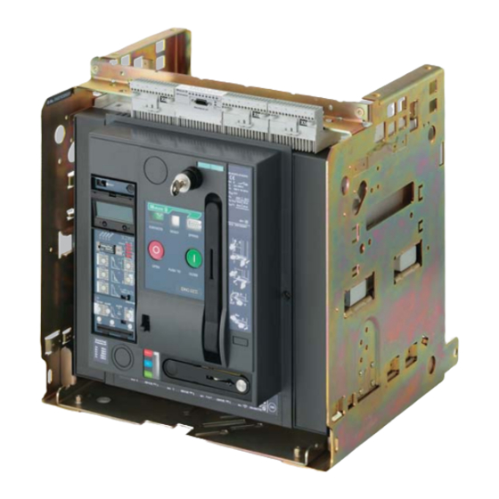
Construction Circuit-breaker Arc chute a page 24 – 4 (15) Earthing terminal a page 5 – 21 Carrying handle (16) Position indicator a page 6 – 2 Identification tags (17) Earth-fault tripping table (a page 9 – 17) Motor cut-off switch (option) a page 14 – 3 or “Electrical ON” (18) Safety lock crank handle (option) a page 15 –... -
Page 10: Withdrawable Unit
Withdrawable unit (18) (17) (16) (15) (14) (13) (12) (11) (10) Arcing chamber cover (option) a page 21 – 1 (11) Door locking withdrawable unit (option) a page 17 – 2 Outlets a page 5 – 19 (12) Guide rail a page 6 – 1 Hole for crane hook a page 4 –... -
Page 11: Labels
Labels Circuit-breaker equipment label (with terminal designations) (Delayed) undervoltage Signalling switch 2nd release or 2nd shunt voltage release release Tripped signalling switch Additional auxiliary contacts Signalling switch 1st voltage release Standard auxiliary 1st shunt release Remote reset contacts Charge condition signalling Ready-to-close Closing release Motor operator... -
Page 12: Identification Of The Control Unit
Identification of the control unit IZM ...-A... Release for protection of systems IZM ...-U... Release for universal protection Options: XT(A) Earth-fault protection N-conductor protection adjustable LCD-display XCOM-DP Communication interface XMP(H) Measurement module IZM...-D... Digital overcurrent release IZM ...-V... Release for selectively-opening circuit- breakers Options: Options:... -
Page 13: Rating Plug Label
Rating plug label Part no. Rated current of the circuit-breaker Withdrawable unit label Part no. Withdrawable unit maximum current rating Position signalling switch Rated insulation voltage Internal handling numbers 08/07 AWB1230-1407GB 2 – 3... - Page 14 2 – 4 08/07 AWB1230-1407GB...
-
Page 15: Standards And Regulations
Standards and regulations Danger Dangerous voltage! Can cause death, serious injury or damage to material/property. Only qualified personnel that are familiar with the warning and safety notices and maintenance instructions may work on the device. Qualified personnel must have the skill and experience in the operation of electrical equipment and systems as well as their construction and function. - Page 16 3 – 2 08/07 AWB1230-1407GB...
-
Page 17: Transport
Transport Unpack the circuit-breaker and inspect for damage. In case of later installation of the circuit-breaker or withdrawable unit: They may be stored and redispatched only in the original packing. Transport packing Red transport indicator Arrow in the top half is partly or fully blue. Arrow in the top half is white –... - Page 18 Lifting by crane Danger Heavy device. Incorrect lifting can cause death or serious injury as well as damage to the device and equipment. Never lift a circuit-breaker, or a withdrawable unit over a person. Follow the operating instructions of the crane. Only use OSHA/ NIOSH tested crane harnesses.
-
Page 19: Mounting
Mounting WARNING Danger Safe operation is dependent upon proper Heavy device. handling and installation by qualified personnel under observance of all warnings contained in Incorrect lifting can cause death or serious this instruction manual. injury as well as damage to the device and equipment. -
Page 20: Mounting On A Vertical Surface With Mounting Brackets
5.1.3 Mounting on a vertical surface with mounting brackets For fixed-mounted circuit-breaker only. Part no. Mounting brackets (only for IZM(IN).1-... and IZM1/2-XTW IZM(IN).2-...) 4 bolts M10-8.8 + nuts + strain washers Non-removable nut 4 bolts M8-8.8 + strain washers Mounting dimensions Representation of IZM(IN).2-... - Page 21 Dimension diagram, mounting brackets o 11 o 13.5 o 20 172.5 17.5 152.5 08/07 AWB1230-1407GB 5 – 3...
-
Page 22: Safety Clearances
5.1.4 Safety clearances 5.1.5 Safety clearance to earthed parts 5.1.5.1 Safety clearances to live parts Rated operational above control Side (each) Rear Rated operational above control Side (each) Rear voltage circuit plug voltage circuit plug [V AC] [mm] [mm] [mm] [V AC] [mm] [mm]... -
Page 23: Use In It Systems
5.1.6 Use in IT systems 5.1.7 Regulations In IEC 60947-2 or EN 60947-2 “Low voltage switchgear Part 2: circuit-breakers” for the use of circuit-breakers in an unearthed or impedance earthed network (IT systems) an extra test to IEC 60947-2 Appendix H is required. Subsequently the tests with 1.2 times the highest setting of the short time delayed overcurrent trip (S trip) or the undelayed overcurrent trip ( I trip) when no S trip is available, as single pole... -
Page 24: Overview
5.1.7.1 Conditions for use in IT Systems The IZM circuit-breaker fulfills the requirements for use in IT safety clearances to the appropriate highest point of the device systems with the standard IEC 60947-2 Appendix H demanded (control circuit plug). The short-circuit breaking capacity shown in maximum values with consideration of the following options and the table I corresponds to the maximum demanded value in the... -
Page 25: Connecting Bars
Connecting bars a Frame sizes, dimension drawings (page 7 – 1) 5.2.1 Horizontal connection The horizontal connection is up to 5000 A including the standard connection for fixed-mounted circuit-breakers and withdrawable unit. o 13.5 mm For withdrawable unit only: a Retrofit installation of horizontal connections (page 5 – 12) 5.2.2 Flange connection (only for withdrawable) -
Page 26: Front Connection
5.2.3 Front connection Note When front connections are used, a partition between busbar and arcing space must be fitted on the system side. Fixed-mounted circuit-breaker Two variations are offered: Standard version: single-hole fitting Version double-hole fitting Holes o 13.5 Fastening connecting bars: 85 Nm 85 Nm Size 5... - Page 27 Withdrawable unit Two variations are offered: Standard version: single-hole fitting Version double-hole fitting Slots for phase separation walls; mounting position as shown! Support Holes o 13.5 Fastening connecting bars: 85 Nm 85 Nm Size 5 Size 5 10 Nm 10 Nm IZM(IN).1-...
-
Page 28: Vertical Connection
5.2.4 Vertical connection Fixed-mounted circuit-breaker Size Rated current IZM(IN).1-... 1000 A 1 × M12-8.8 + nut 1600 A + spring washer (above + below) 85 Nm 1) 2 connection bars per main connection, above and below fixing by offset slot, a Picture for IZM(IN).2-... - Page 29 Withdrawable unit Size Size Size Rated current Rated current Rated current IZM(IN).1-... 1000 A, 1600 A IZM(IN).2-... 2000 A, 2500 A IZM(IN).3-... 5000 3200 1 × M 6 2 × M 6 2 × M 6 2 x o 13.5 3 x o 13.5 4 x o 13.5 Vertical connections left and right...
- Page 30 Removing horizontal connection Rear drawer area Size 5 Combination screw M6x20 Installing vertical connection Rear drawer area Combination screw M6x20 8 Nm Mounting steps for installation of horizontal or flange connection are similar. Note The lamelle blocks for circuit-breaker IZM(IN).3-..., 4000 A, are not fully equiped with lamelle.
-
Page 31: Order Numbers
Order numbers Connecting bars fixed-mounted circuit-breaker Frame size Rated current I Part no. F 1000 A (+)IZM1-XAT1F10-0 IZM(IN).1-... 1250 A...1600 A (+)IZM1-XAT1F16-0 F 2000 A (+)IZM2-XAT1F20-0 Front connection (single-hole fitting) top IZM(IN).2-... 2500 A (+)IZM2-XAT1F25-0 3200 A (+)IZM2-XAT1F32-0 IZM(IN).3-... F 4000 A (+)IZM3-XAT1F40-0 F 1000 A (+)IZM1-XATF10-0... -
Page 32: Displays
Connecting bars withdrawable unit Frame size Rated current I Part no. F 1000 A (+)IZM1-XAT1F10-AV IZM(IN).1-... 1250 A...1600 A (+)IZM1-XAT1F16-AV Front connection (single-hole fitting) F 2000 A (+)IZM2-XAT1F20-AV When these connections are ordered individually, additional IZM(IN).2-... 2500 A (+)IZM2-XAT1F25-AV supports must also be ordered. 3200 A (+)IZM2-XAT1F32-AV IZM(IN).3-... -
Page 33: Connection Of Main Conductors
Connection of main conductors Cleaning the copper bars Main conductor - minimum cross section: Metal cuttings Steel-wire brush Frame size Rated current Cross section Cu bars Remove bare/bare black/bare [mm2] [mm2] 1 × 40 × 10 1 × 40 × 10 1 ×... -
Page 34: Auxiliary Conductor Connection
Auxiliary conductor connection Retrofitting Terminal assignment: a Circuit diagrams (page 8 – 1) Cross section connection type Strip conductors Screw terminals 0.5 – 2.5 mm 0.5 – 1.5 mm AWG 20...14 AWG 20...15 Wire end ferrule Wire end ferrule 7 mm Spring-loaded 0.5 –... -
Page 35: Sliding Contact Module
Spring-loaded terminals 5.4.3 Control circuit plug Screw terminals 3.0 × 0.6 Connecting wires 3.0 × 0.6 5.4.2 Sliding contact module Spring-loaded terminals Retrofitting 3.0 × 0.6 2 terminals in parallel per contact Attach guide tongues (fixed-mounted circuit-breaker only) Connection area with sliding contact modules Back side of Sliding contact module auxiliary connector... - Page 36 Coding (only fixed-mounted circuit-breakers) Groove Guide Modul labelling (here X5; must show at front) Module X5 Fitting auxiliary connectors Control circuit plug Fixed mounting: Knife contact rail Withdrawable: Sliding contact module 5 – 18 08/07 AWB1230-1407GB...
-
Page 37: Wiring On Withdrawable Unit
5.4.4 Wiring on withdrawable unit Danger Impermissible area for wires: Wires could be damaged. Arcing space*) Carrying ha Outlets Interlocks *)When arc chute cover is used control circuit wires must not be laid on this cover.. 5.4.5 Assembly with control circuit connections 5.4.6 Order numbers Terminal X6 always available. - Page 38 Connection possibilities of the control circuit connections Fixed mounted Connection with screw terminals Screwless connection (spring- (standard) loaded terminals) (option) IZM-XKL-HS IZM-XKL-HZ Coding (only for fixed mounting) IZM-XKL-C Plug connector on basic unit IZM-XKL-ML Withdrawable units Connection with screw terminals Screwless connection (spring- (option) loaded terminals) (option)
-
Page 39: Changeover Of Fixed Mounting Circuit-Breaker
Connection of protective conductor 5.5.1 Fixed-mounted circuit-breaker 14 mm 5.5.2 Withdrawable unit 14 mm Changeover of fixed mounting circuit-breaker into withdrawable circuit-breaker Note For the changeover of your circuit-breaker our Field Service can be used. To contact Field Service: a chapter 26. –... - Page 40 5.6.1 Conversion Replacing circuit-breaker feet Size 5 Size 4 1 Install racking mechanism 2 When threaded holes exist bolt the racking mechanism tight with M6x12 cheese-head screw, strain washer and 6x18x3 washer. When no screw thread exists grease a self-tapping screw and screw in.
- Page 41 Knock out front panel Conversion kit part numbers Conversion kit for fixed-mounted into withdrawable circuit-breaker. Frame size Part no. IZM(IN).1-... IZM1-XUS-AV IZM(IN).1-4-... IZM1-XUS4-AV IZM(IN).2-... IZM2-XUS-AV IZM(IN).2-4-... IZM2-XUS4-AV IZM(IN).3-... IZM3-XUS-AV IZM(IN).3-4-... IZM3-XUS4-AV Note Conversion kits can only be ordered using the part no. shown above and also giving the Indent no.
- Page 42 5 – 24 08/07 AWB1230-1407GB...
Need help?
Do you have a question about the IZM1 Series and is the answer not in the manual?
Questions and answers