Table of Contents
Advertisement
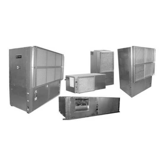
Installation, Operation and Maintenance
Water Source Heat Pump
Axiom™ Horizontal/Vertical
GEH/V*, EXH/V*
0.5 to 25 Tons, 50/60 Hz
GEHE 006-060 - 50/60 Hz
Model Numbers:
GEVE 006-060 - 50/60 Hz
GEHE 072-180 - 50/60 Hz
GEVE 072-300 - 50/60 Hz
EXHF 006-070 - 60 Hz
EXVF 006-070 - 60 Hz
Only qualified personnel should install and service the equipment. The installation, starting up, and servicing of
heating, ventilating, and air-conditioning equipment can be hazardous and requires specific knowledge and training.
Improperly installed, adjusted or altered equipment by an unqualified person could result in death or serious injury.
When working on the equipment, observe all precautions in the literature and on the tags, stickers, and labels that are
attached to the equipment.
December 2020
SAFETY WARNING
WSHP-SVX01W-EN
Advertisement
Table of Contents

Related Manuals for Trane Technologies Axiom GEH Series


Summary of Contents for Trane Technologies Axiom GEH Series
- Page 1 Installation, Operation and Maintenance Water Source Heat Pump Axiom™ Horizontal/Vertical GEH/V*, EXH/V* 0.5 to 25 Tons, 50/60 Hz GEHE 006-060 - 50/60 Hz Model Numbers: GEVE 006-060 - 50/60 Hz GEHE 072-180 - 50/60 Hz GEVE 072-300 - 50/60 Hz EXHF 006-070 - 60 Hz EXVF 006-070 - 60 Hz SAFETY WARNING...
- Page 2 Introduction Read this manual thoroughly before operating or servicing this unit. WARNING Proper Field Wiring and Grounding Warnings, Cautions, and Notices Required! Safety advisories appear throughout this manual as Failure to follow code could result in death or serious required. Your personal safety and the proper operation of injury.
- Page 3 Introduction WARNING Follow EHS Policies! Failure to follow instructions below could result in death or serious injury. • All Trane personnel must follow the company’s Environmental, Health and Safety (EHS) policies when performing work such as hot work, electrical, fall protection, lockout/tagout, refrigerant handling, etc.
-
Page 4: Table Of Contents
Table of Contents Model Number Descriptions - 0.5 to 25 Tons Waterside Economizer Installation for GEH and GEV 6 to 25 Ton Models ...65 Model Number Descriptions - 0.5 to 6 Tons Waterside Economizer Start-Up Sequence Overview of Manual . -
Page 5: Model Number Descriptions - 0.5 To 25 Tons
Model Number Descriptions - 0.5 to 25 Tons Digits 1, 2, 3 — Unit Digit 12 — Blower Configuration Digit 20 — Temperature Sensor Configuration Standard blower motor No temperature sensor High static blower motor Entering water sensor GEH= Standard efficiency horizontal Drive package A 0.5 to 15 tons Digit 21 —... -
Page 6: Model Number Descriptions - 0.5 To 6 Tons
Model Number Descriptions - 0.5 to 6 Tons Digits 1, 2, 3 — Unit Digit 16 — Return-Air Configuration Arrangement EXH= High efficiency horizontal Left return-air arrangement EXV= High efficiency vertical Right return-air arrangement — Digit 4 Development Sequence Digit 17 — Control Types Deluxe 24V controls Tracer®... -
Page 7: Overview Of Manual
Overview of Manual Compressor Nameplate Note: One copy of this document ships with each unit and is customer property. It must be retained by the The nameplate for the compressors are located on the unit’s maintenance personnel. compressor shell. This booklet describes proper installation, operation, and Model Number Description maintenance procedures for HVAC systems. -
Page 8: General Information
General Information Unit Description compressor disable, condensate overflow, unit safety control, diagnostics, and a generic relay (which may be Before shipment, each unit is leak tested, dehydrated, available for field use). See Table 65, p. 112 for diagnostic charged with refrigerant and run tested for proper control information and Figure 56, p. - Page 9 General Information controller returns the unit to normal compressor heating Table 2. 6 to 25 ton GEH/V fan speed for two-speed operation, and locks out the electric heater. drive packages one to nine For units comprised of the field installed duct heater RV State Compressor 1 Compressor 2 Fan Speed option, the unit will ship from the factory with controls...
- Page 10 General Information Table 3. Refrigerant charge Model Heat Pump Heat Pump w/HGR (60 Hz) (oz)/(Kg) (oz)/(Kg) Circuit 1 Circuit 2 Circuit 1 Circuit 2 GEHE006 25.3 / 0.717 ----- 26.8 / 0.760 ----- GEHE009 26.0 /0.737 ----- 27.5 / 0.780 ----- GEHE012 28.5 / 0.808...
- Page 11 General Information Table 3. Refrigerant charge (continued) Model Heat Pump Heat Pump w/HGR (60 Hz) (oz)/(Kg) (oz)/(Kg) EXVF006 25.7 / 0.729 ----- 27.2 / 0.771 ----- EXVF009 26.5 / 0.751 ----- 28.0 / 0.794 ----- EXVF012 29.5 / 0.836 ----- 31.5 / 0.893 ----- EXVF015...
-
Page 12: Pre-Installation
Pre-Installation the jobsite, the unit(s) are now the property of the SOLD TO party and future freight claims MAY NOT be WARNING accepted by the freight company. Fiberglass Wool! Jobsite Storage Exposition to glass wool fibers without all necessary PPE equipment could result in cancer, respiratory, skin or eye irritation, which could result in death or serious NOTICE injury. -
Page 13: Unit Dimensions
Unit Dimensions Service Clearances Per NEC requirements, 36 inches of access and working space shall be provided and maintained around all control boxes and electrical equipment to permit ready and safe operation and maintenance of such equipment. Local codes may require more clearance to electrical equipment. - Page 14 Unit Dimensions Figure 3. Clearance - GEV 0.5 to 5 tons and EXV 0.5 to 6 tons A 24 inch clearance from other mechanical and electrical 1" equipment (where shown) is recommended for all configurations. This will enable panel removal from the unit for service/maintenance.
- Page 15 Unit Dimensions Figure 6. Left return/left supply (GEH/EXH) F X G OPENING REFRIG BLOWER CONTROL ACCESS ACCESS PANEL HI VOLT L (W.O.) WCI mounting location LO VOLT M (W.I.) DRAIN 3/4" NPTI LEFT SIDE BACK FRONT 14" RIGHT SIDE Table 4. Dimensional data left return/left supply (GEH/EXH) GEH Unit GEH Unit (60 Hz)
- Page 16 Unit Dimensions Figure 7. Left return/back supply (GEH/EXH) F X G OPENING REFRIG BLOWER CONTROL ACCESS ACCESS PANEL HI VOLT L (W.O.) WCI mounting location LO VOLT M (W.I.) DRAIN BACK LEFT SIDE FRONT 3/4" NPTI 14" RIGHT SIDE Table 5. Dimensional data left return/back supply (GEH/EXH) GEH Unit GEH Unit (60 Hz)
- Page 17 Unit Dimensions Figure 8. Left return/right supply (GEH/EXH) REFRIG CONTROL BLOWER ACCESS ACCESS PANEL HI VOLT L (W.O.) WCI mounting location LO VOLT M (W.I.) DRAIN BACK LEFT SIDE FRONT F X G 3/4" NPTI OPENING 14" RIGHT SIDE Table 6. Dimensional data left return/right supply (GEH/EXH) GEH Unit GEH Unit (60 Hz)
- Page 18 Unit Dimensions Figure 9. Right return/left supply (GEH/EXH) REFRIG CONTROL F X G BLOWER ACCESS OPENING ACCESS PANEL HI VOLT WCI mounting location LO VOLT L (W.O.) BACK LEFT SIDE FRONT DRAIN M (W.I.) 3/4" NPTI 14" RIGHT SIDE Table 7. Dimensional data right return/left supply (GEH/EXH) Unit (60 Unit (50 F x G...
- Page 19 Unit Dimensions Figure 10. Right return/back supply (GEH/EXH) F X G OPENING REFRIG BLOWER ACCESS CONTROL PANEL ACCESS HI VOLT 14" WCI mounting location LO VOLT L (W.O.) DRAIN M (W.I.) BACK LEFT SIDE FRONT 3/4" NPTI RIGHT SIDE Table 8. Dimensional data right return/back supply (GEH/EXH) GEH Unit GEH Unit (60 Hz)
- Page 20 Unit Dimensions Figure 11. Right return/right supply (GEH/EXH) REFRIG CONTROL BLOWER ACCESS ACCESS PANEL HI VOLT WCI mounting location LO VOLT L (W.O.) F X G LEFT SIDE BACK OPENING FRONT DRAIN M (W.I.) 3/4" NPTI RIGHT SIDE Table 9. Dimensional data right return/right supply (GEH/EXH) GEH Unit GEH Unit (60 Hz)
- Page 21 Unit Dimensions Figure 12. Left return/top supply (GEV/EXV) BLOWER ACCESS COMP/CONTROL ACCESS W.O. WCI mounting location DRAIN HI VOLT 12” 9 1/2” 8 3/4” LO VOLT W.I. 3 5/8” 8 5/8” LEFT SIDE FRONT RIGHT SIDE Table 10. Dimensional data left return/top supply (GEV/EXV) GEV Unit GEV Unit W.I.
- Page 22 Unit Dimensions Figure 13. Left return/back supply (GEV/EXV) BLOWER ACCESS COMP/CONTROL ACCESS WCI mounting location W.O. DRAIN HI VOLT 12” 9 1/2” 8 3/4” LO VOLT W.I. 3 5/8” 3 5/8” LEFT SIDE FRONT RIGHT SIDE Table 11. Dimensional data left return/back supply (GEV/EXV) GEV Unit GEV Unit W.I.
- Page 23 Unit Dimensions Figure 14. Right return/top supply (GEV/EXV) BLOWER ACCESS COMP/CONTROL ACCESS W.O. WCI mounting location DRAIN HI VOLT 9 1/2” 12” 8 3/4” LOW VOLT W.I. 3 5/8” 3 5/8” RIGHT SIDE FRONT LEFT SIDE Table 12. Right return/top supply (GEV/EXV) GEV Unit GEV Unit W.I.
- Page 24 Unit Dimensions Figure 15. Right return/back supply (GEV/EXV) BLOWER ACCESS COMP/CONTROL ACCESS W.O. WCI mounting location DRAIN HIGH VOLT 9 1/2” 12” 8 3/4” LOW VOLT W.I. 3 5/8” 3 5/8” RIGHT SIDE LEFT SIDE FRONT Table 13. Dimensional data right return/back supply (GEV/EXV) GEV Unit GEV Unit W.I.
- Page 25 Unit Dimensions Figure 16. Right return/left supply - GEH 6 to 10 tons (60 Hz); GEH 6 to 7.5 tons (50 Hz) 79” 1 3/4” 74 1/2” 40 5/8” 36” 23 7/8” 7 5/8” BLOWER ACCESS TOP VIEW PANEL 18 3/8” 81”...
- Page 26 Unit Dimensions Figure 17. Right return/back supply - GEH 6 to 10 tons (60 Hz); GEH 6 to 7.5 tons (50 Hz) 79” 74 1/2” 1 3/4” 40 5/8” 36” 18 3/8” 23 7/8” 81” 85” BLOWER ACCESS TOP VIEW PANEL W.O.
- Page 27 Unit Dimensions Figure 18. Left return/right supply GEH 6 to 10 tons (60 Hz); GEH 6 to 7.5 tons (50 Hz) 79” 74 1/2” 1 3/4” 40 5/8” 36” 24 3/4” 7 5/8” BLOWER ACCESS TOP VIEW PANEL 18 3/8” 81”...
- Page 28 Unit Dimensions Figure 19. Left return/back supply GEH 6 to 10 tons (60 Hz); GEH 6 to 7.5 tons (50 Hz) 79” 74 1/2” 1 3/4” 40 5/8” 36” 18 3/8” 24 3/4” 81” 85” TOP VIEW BLOWER ACCESS PANEL W.O.
- Page 29 Unit Dimensions Figure 20. Right return/left supply GEH 12.5 to 15 tons (150-180) 60 Hz; GEH 10 to 12.5 tons (120-150) 50 Hz 85" 2" 74 1/2" 46 5/8" 42" 29 3/4" 7 1/8" BLOWER ACCESS TOP VIEW PANEL 21 3/8" 87"...
- Page 30 Unit Dimensions Figure 21. Right return/back supply GEH 12.5 to 15 tons (60 Hz); GEH 10 to 12.5 tons (50 Hz) 85" 74 1/2" 2" 46 5/8" 42" 29 3/4" 21 3/8" 87" 91" TOP VIEW BLOWER ACCESS PANEL W.O. 1 1/2” NPTI 24 VOLT 61 1/4"...
- Page 31 Unit Dimensions Figure 22. Left return/right supply GEH 12.5 to 15 tons (60 Hz); GEH 10 to 12.5 tons (50 Hz) 85” 2" 74 1/2” 46 5/8” 42” 29 3/4” 7 1/8” BLOWER ACCESS TOP VIEW PANEL 21 3/8” 87” 91”...
- Page 32 Unit Dimensions Figure 23. Left return/back supply GEH 12.5 to 15 tons (60 Hz); GEH 10 to 12.5 tons (50 Hz) 85" 74 1/2" 2" 46 5/8" 42" 21 3/8" 29 3/4" 87" 91" TOP VIEW BLOWER ACCESS PANEL W.O. 1 1/2" NPTI 24 VOLT 2 1/8"...
- Page 33 Unit Dimensions Figure 24. Front return/back supply GEV 6 to 10 tons (60 Hz); 6 and 7.5 tons (50 Hz) 15 3/4” SUPPLY OPENING 1" DUCT FLANGE 13 18" ACCESS PANEL FOR SHEAVES AND BELTS 31 3/8" 36 1/4" 39 5/8" 42"...
- Page 34 Unit Dimensions Figure 25. Front return/top supply GEV 6 to 10 tons (60 Hz); 6 and 7.5 tons (50 Hz) 15 5/8 ACCESS PANEL FOR SHEAVES AND BELTS 13 1/4" 13 3/8" 31 3/8" 36 1/4" 39 5/8" 42" 38 7/8" 63"...
- Page 35 Unit Dimensions Figure 26. Back return/front supply GEV 6 to 10 tons (60 Hz); 6 and 7.5 ton (50 Hz) 39 5/8" ACCESS PANEL FOR SHEAVES AND BELTS 36 1/4" 31 3/8" 13 1/8" 15 3/4” 42" 1" 38 7/8" W.O.
- Page 36 Unit Dimensions Figure 27. Back return/top supply GEV 6 to 10 tons (60 Hz); 6 and 7.5 ton (50 Hz) 39 5/8" ACCESS PANEL FOR SHEAVES AND BELTS 36 1/4" 31 3/8" 13 1/2" 13 1/4" 15 5/8” 42" 38 7/8" W.O.
- Page 37 Unit Dimensions Figure 28. Front return/back supply GEV 12.5 to 15 tons (60 Hz); GEV 10 and 12.5 ton (50 Hz) 31 1/2" 36 1/4" 10" 74 1/2" 4 3/4" 81 5/8" TOP VIEW 18 5/8" 31 1/2" 24 VOLT 15 7/8"...
- Page 38 Unit Dimensions Figure 29. Back return/front supply GEV 12.5 to 15 tons (60 Hz); GEV 10 and 12.5 ton (50 Hz) 81 5/8" 4 3/4" 74 1/2" 36 1/4" 31 1/2" 10" TOP VIEW 18 5/8" 31 1/2" 15 7/8" 38 7/8"...
- Page 39 Unit Dimensions Figure 30. Front return/top supply GEV 12.5 to 15 tons (60 Hz); GEV 10 and 12.5 ton (50 Hz) 15 7/8" 31 1/2" 36 1/4" 14 3/8" 10" 74 1/2" 4 3/4" 81 5/8" TOP VIEW 18 5/8" 31 1/2"...
- Page 40 Unit Dimensions Figure 31. Back return/top supply GEV 12.5 to 15 tons (60 Hz); GEV 10 and 12.5 ton (50 Hz) 81 5/8" 4 3/4" 74 1/2" 14 3/8" 36 1/4" 31 1/2" 15 7/8" 10" TOP VIEW 18 5/8" 31 1/2"...
- Page 41 Unit Dimensions Figure 32. Front return/back supply GEV 20 and 25 ton (60 Hz); GEV 15 and 20 ton (50 Hz) 31 1/2" 36 1/4" 6 1/4" 74 1/2" 4 3/4" 81 5/8" TOP VIEW 19 1/8” 24 VOLT 1 1/8" O.D. 38 7/8"...
- Page 42 Unit Dimensions Figure 33. Back return/front supply GEV 20 and 25 ton (60 Hz); GEV 15 and 20 ton (50 Hz) 81 5/8" 4 3/4" 74 1/2" 36 1/4" 31 1/2" 6 1/4" TOP VIEW 38 7/8" W.O. 2" NPTI 67 5/8"...
- Page 43 Unit Dimensions Figure 34. Front return/top supply GEV 20 and 25 ton (60 Hz); GEV 15 and 20 ton (50 Hz) 31 1/2" 36 1/4" 6 1/4" 74 1/2" 4 3/4" 81 5/8" TOP VIEW 19 1/8" 38 7/8" W.O. 2" NPTI 68"...
- Page 44 Unit Dimensions Figure 35. Back return/top supply GEV 20 and 25 ton (60 Hz); GEV 15 and 20 ton (50 Hz) 81 5/8" 4 3/4" 74 1/2" 36 1/4" 31 1/2" 6 1/4" TOP VIEW 19 1/8" 38 7/8" W.O. 2" NPTI 68"...
- Page 45 Unit Dimensions Figure 36. Waterside economizer (GEH/EXH) TOP VIEW 20" A = TO FIELD SUPPLY PIPING B = TO FIELD RETURN PIPING FRONT VIEW 5" (a) Waterside economizer installation requires field piping. Table 26. Dimensional data waterside economizer (GEH/EXH) (60 Hz) (50 Hz) A NPTI B NPTI 006-015 006-012 16-7/8...
- Page 46 Unit Dimensions Figure 37. Hanging unit waterside economizer (GEH/EXH) Table 27. Dimensional data hanging unit waterside economizer (GEH/EXH) GEH Unit GEH Unit Hanging Shipping (60 Hz) (50 Hz) Weight Weight 006-015 006-012 38-3/4 18-3/4 22-1/8 17-1/2 44 lbs 95 lbs 018-030 015-024 44-3/4...
- Page 47 Unit Dimensions Figure 38. GEH 6 to 10 tons (60 Hz), GEH 6 to 7.5 tons (50 Hz) - right return with waterside economizer 9 7/8" 18 1/2" 50 5/8" 36" 23 7/8" "B" OD COPPER TO FIELD SUPPLY PIPING "A"...
- Page 48 Unit Dimensions Figure 40. GEH 12.5 to 15 tons (60 Hz), GEH 10 to 12.5 tons (50 Hz), right return with waterside economizer 9 7/8" 18 1/2" 56 1/2" 42" 29 3/4" 48 3/4" 1 5/8" OD COPPER TO FIELD SUPPLY PIPING 1 1/2"...
- Page 49 Unit Dimensions Figure 41. GEH 12.5 to 15 tons (60 Hz), GEH 10 to 12.5 tons (50 Hz), left return with waterside economizer 9 7/8" 18 1/2" 56 1/2" 42" 29 3/4" 27 1/8" 1 5/8" OD COPPER TO FIELD SUPPLY PIPING 1 1/2"...
- Page 50 Unit Dimensions Figure 42. GEV 6 to 10 tons (60 Hz), 6 and 7.5 tons (50 Hz) - waterside economizer A = TO FIELD RETURN PIPING B = TO FIELD SUPPLY PIPING 2 1/4" Table 31. Dimensional data GEV 6 to 10 tons (60 Hz), 6 and 7.5 tons (50 Hz) - waterside economizer Hanging Shipping Unit (60 Hz)
- Page 51 Unit Dimensions Figure 43. GEV 12.5 to 25 tons - waterside economizer 13" TOP VIEW A = TO FIELD RETURN PIPING B = TO FIELD SUPPLY PIPING 2 3/4" SIDE VIEW FRONT VIEW Table 32. Dimensional data GEV 12.5 to 25 tons - waterside economizer GEV (60 Hz) GEV (50 Hz) NPTI...
- Page 52 Unit Dimensions Figure 44. Waterside economizer coil piping diagram Note: (applicable only to 6 to 25 ton models) Unit WSE Coil WSE Coil Unit Water Outlet Inlet Water Outlet Inlet Unit Heat Coil Exchanger Port A Port AB 3 Way Valve Please match the entering water port marking with...
-
Page 53: Weights
Weights Table 36. Unit weights EXH 0.5 to 6 tons (continued) Table 33. Unit weights GEH 0.5 to 5 tons Shipping Weight with Unit Weight without Shipping Weight with Unit Weight without EXH (60 Hz) pallet (lbs) pallet (lbs) GEH (60 Hz) pallet (lbs) pallet (lbs) Weight Distribution for Hanging the GEH... -
Page 54: Installation
Installation Main Electrical WARNING Proper Field Wiring and Grounding WARNING Required! Hazardous Voltage! Failure to follow code could result in death or serious Failure to disconnect power before servicing could injury. All field wiring MUST be performed by qualified result in death or serious injury. Disconnect all electric personnel. -
Page 55: Return-Air Ductwork
Installation Supply-Air Ductwork Figure 48. Flexible return-air connector (field provided) GEV return duct Horizontal 0.5 to 5 ton and EXHF units require duct flanges to be field installed. The duct flange ships in a box on the side of the unit. Install the flange with (8) 3/8 in. factory supplied screws. -
Page 56: Ducted Filter Rack (Geh 0.5 To 5 Tons And Exh 0.5 To 6 Ton Only)
Installation Table 39. Ducted filter opening size (continued) Figure 50. Install return-air duct panel Unit Size A (in.) B (in.) C (in.) Install the return- Unit Top GEV 048-060 30.7 26.6 air duct panel to EXH 006-015 21.1 15.4 the return-air opening with the EXH 018-030 24.5... -
Page 57: Condensate Drain Connection
Installation 2. Secure the equipment to a joist, concrete, etc. with the until there is a constant flow. It is imperative to maintain use of 3/8 in. field provided (all-thread) rod. Each water in the trap and not allow the trap to dry out during corner should contain field provided nuts and washers heating season. -
Page 58: Field Installed Power Wiring
Installation water leaving the drain runs clear, but not less than 2 Figure 54. Power wiring example hours. 6. Shut down pumps and supplementary heat system. FIELD CONNECTIONS Reconnect the hoses placing the water-to-refrigerant heat exchanger in the water circulating system. Note: Vents should be open when the pumps and supplementary heat system are shut down. -
Page 59: Controls Using 24 Vac
Installation • Near radiant heat (heat emitted from appliances or the Figure 57. Low-voltage connection (GEH/V 6 to 25 ton) sun) • Near concealed pipes or chimneys Deluxe Controls with Deluxe Controls with -all Heat Pump Units w/ Reheat -all Heat Pump Units w/ Reheat using X13511090010 (T8511) using X13511091010/X13511092010 (T7300) •... -
Page 60: Hole Plug Installation
Installation Table 42. 3-speed motor (380, 415, 460) WARNING Lead Colors Proper Field Wiring and Grounding Lead Black Blue Orange Required! Speed High Medium Failure to follow code could result in death or serious Note: When using the medium or low speed tap, the purple wire must be injury. - Page 61 Installation To adjust the cfm, disconnect the power to the unit. Set the Figure 59. Fan motor and sheave adjustment DIP switch located in the control box to the desired profile Belt setting. Connect the power to the unit. 2.Adjustment Bolt and Profile A = 110% of rated airflow Plate Profile B = 100% of rated airflow...
-
Page 62: Waterside Economizer Installation
Installation Waterside Economizer Installation Note: Waterside economizer option is configured for right return. Left return requires additional field Note: GEH 0.5 to 5 and EXH 0.5 to 6 ton units. piping. Figure 63. Step 4 WARNING Hazardous Voltage! Failure to disconnect power before servicing could result in death or serious injury. - Page 63 Installation 7. Verify the control board for the water side economizer Figure 68. Step 9 is located at the back of the control box. The temperature rating of this board is factory set to 55ºF. For units with boilerless (electric heat) control and water side economizer, the boilerless control board is factory set to 45ºF.
- Page 64 Installation condensation from forming on the pipe and dripping Figure 71. Step 12 onto the ceiling tiles. Notes: • Trane does not provide insulation on the economizing piping package. This insulation must be field provided and field installed. • Trane does not provide condensate overflow protection of the waterside economizer.
-
Page 65: Waterside Economizer Installation For Geh And Gev 6 To 25 Ton Models
Installation Waterside Economizer Installation for GEH capable of reading the actual entering water temperature regardless of the economizer’s on or off and GEV 6 to 25 Ton Models situation. 12. Insulate the thermistor with tubing insulation. WARNING 13. Tie wrap each end of the tubing insulation to prevent Hazardous Voltage! air filtration. -
Page 66: Waterside Economizer Start-Up Sequence
Waterside Economizer Start-Up Sequence 1. Set the thermostat to the highest position. 6. Leave unit off for approximately FIVE minutes to allow for pressure equalization. 2. Set the thermostat system switch to COOL with the fan control to AUTO. The compressor should NOT run. 7. - Page 67 Waterside Economizer Start-Up Sequence Table 47. Waterside economizing three-way valve specifications Valve Conn. Valve Pres. Valve Close-off Valve Temp. Unit Size (60 Hz) Unit Size (50 Hz) Size Rating pressure Range Actuator Non-spring return type 0ºF to 212ºF 24 Vac +/- 20% GEH006-015 GEH006-012 1/2 FPT...
-
Page 68: Electrical Data
Electrical Data Table 48. Electrical data standard static motors (0.5 to 25 tons), single speed blower motor (6 to 25 tons) Maximum Total Comp Comp Blower Blower Minimum Overcurrent Electric Electric Unit No. of Motor Motor Circuit Protective Heat Heat Model Volts (ea) - Page 69 Electrical Data Table 48. Electrical data standard static motors (0.5 to 25 tons), single speed blower motor (6 to 25 tons) (continued) Maximum Total Comp Comp Blower Blower Minimum Overcurrent Electric Electric Unit No. of Motor Motor Circuit Protective Heat Heat Model Volts...
- Page 70 Electrical Data Table 48. Electrical data standard static motors (0.5 to 25 tons), single speed blower motor (6 to 25 tons) (continued) Maximum Total Comp Comp Blower Blower Minimum Overcurrent Electric Electric Unit No. of Motor Motor Circuit Protective Heat Heat Model Volts...
- Page 71 Electrical Data Table 48. Electrical data standard static motors (0.5 to 25 tons), single speed blower motor (6 to 25 tons) (continued) Maximum Total Comp Comp Blower Blower Minimum Overcurrent Electric Electric Unit No. of Motor Motor Circuit Protective Heat Heat Model Volts...
- Page 72 Electrical Data Table 48. Electrical data standard static motors (0.5 to 25 tons), single speed blower motor (6 to 25 tons) (continued) Maximum Total Comp Comp Blower Blower Minimum Overcurrent Electric Electric Unit No. of Motor Motor Circuit Protective Heat Heat Model Volts...
- Page 73 Electrical Data Table 48. Electrical data standard static motors (0.5 to 25 tons), single speed blower motor (6 to 25 tons) (continued) Maximum Total Comp Comp Blower Blower Minimum Overcurrent Electric Electric Unit No. of Motor Motor Circuit Protective Heat Heat Model Volts...
- Page 74 Electrical Data Table 48. Electrical data standard static motors (0.5 to 25 tons), single speed blower motor (6 to 25 tons) (continued) Maximum Total Comp Comp Blower Blower Minimum Overcurrent Electric Electric Unit No. of Motor Motor Circuit Protective Heat Heat Model Volts...
- Page 75 Electrical Data Table 49. Electrical data high static motors 0.5 to 5 tons Maximum Total Comp Comp Blower Blower Minimum Overcurrent Electric Electric Model Unit No. of Motor Motor Motor Circuit Protective Heat Heat Volts (ea) (ea) Comp. Ampacity Device Amps GEH/V006 115/60/1...
- Page 76 Electrical Data Table 49. Electrical data high static motors 0.5 to 5 tons (continued) Maximum Total Comp Comp Blower Blower Minimum Overcurrent Electric Electric Model Unit No. of Motor Motor Motor Circuit Protective Heat Heat Volts (ea) (ea) Comp. Ampacity Device Amps GEH/V030...
- Page 77 Electrical Data Table 49. Electrical data high static motors 0.5 to 5 tons (continued) Maximum Total Comp Comp Blower Blower Minimum Overcurrent Electric Electric Model Unit No. of Motor Motor Motor Circuit Protective Heat Heat Volts (ea) (ea) Comp. Ampacity Device Amps GEH/V042...
- Page 78 Electrical Data Table 50. Electrical data - ECM motors - 0.5 to 6 tons EXH*/EXV* (continued) Maximum Total Comp Comp Blower Blower Minimum Overcurrent Model Unit Motor Motor Circuit Protective Electric Electric Volts (ea) (ea) Ampacity Device Heat kW Heat Amps EXH012 230/60/1 9.42...
- Page 79 Electrical Data Table 50. Electrical data - ECM motors - 0.5 to 6 tons EXH*/EXV* (continued) Maximum Total Comp Comp Blower Blower Minimum Overcurrent Model Unit Motor Motor Circuit Protective Electric Electric Volts (ea) (ea) Ampacity Device Heat kW Heat Amps EXH042 230/60/3 24.48...
- Page 80 Electrical Data Table 50. Electrical data - ECM motors - 0.5 to 6 tons EXH*/EXV* (continued) Maximum Total Comp Comp Blower Blower Minimum Overcurrent Model Unit Motor Motor Circuit Protective Electric Electric Volts (ea) (ea) Ampacity Device Heat kW Heat Amps EXV012 208/60/1 8.45...
- Page 81 Electrical Data Table 50. Electrical data - ECM motors - 0.5 to 6 tons EXH*/EXV* (continued) Maximum Total Comp Comp Blower Blower Minimum Overcurrent Model Unit Motor Motor Circuit Protective Electric Electric Volts (ea) (ea) Ampacity Device Heat kW Heat Amps EXV042 208/60/3 22.44...
- Page 82 Electrical Data Table 51. Electrical data two speed blower motor 6 to 25 tons (continued) Maximum Comp Blower Blower Minimum Overcurrent Model Total Comp RLA No. of Motor Motor Motor Circuit Protective Volts (ea) (ea) Comp. Cmp MCC Ampacity Device GEH072 460/60/3 13.8...
- Page 83 Electrical Data Table 51. Electrical data two speed blower motor 6 to 25 tons (continued) Maximum Comp Blower Blower Minimum Overcurrent Model Total Comp RLA No. of Motor Motor Motor Circuit Protective Volts (ea) (ea) Comp. Cmp MCC Ampacity Device GEH180 208/60/3 64.6...
- Page 84 Electrical Data Table 51. Electrical data two speed blower motor 6 to 25 tons (continued) Maximum Comp Blower Blower Minimum Overcurrent Model Total Comp RLA No. of Motor Motor Motor Circuit Protective Volts (ea) (ea) Comp. Cmp MCC Ampacity Device GEV150 230/60/3 58.0...
-
Page 85: Pre-Start Checklist
Pre-Start Checklist Before energizing the unit, the following system devices • Are the low/high-side pressure temperature caps must be checked: secure and in place? • Is the high voltage power supply correct and in • Are all the unit access panels secure and in place? accordance with the nameplate ratings? •... -
Page 86: Start-Up
Start-Up Initial Unit Start-up Table 53. Checklist (continued) MODE Heat Cool Note: Start-up with the heat pump thermostat is included Water coil heat exchanger (Water ________PSIG ________PSIG below: Pressure OUT) 1. Is phasing of the unit correct per compressor rotation _________PSI _________PSI Pressure Differential... - Page 87 Start-Up Table 54. Operating pressures in cooling/heating for GE* units Operating Data Cooling Heating Entering Water Water Water Water Suction Discharge Temp Air Temp Suction Discharge Temp Temp Temp Flow Pressure Pressure Rise Drop Pressure Pressure Drop Rise Model No. (°F) (GPM) (psig)
- Page 88 Start-Up Table 54. Operating pressures in cooling/heating for GE* units (continued) Operating Data Cooling Heating Entering Water Water Water Water Suction Discharge Temp Air Temp Suction Discharge Temp Temp Temp Flow Pressure Pressure Rise Drop Pressure Pressure Drop Rise Model No. (°F) (GPM) (psig)
- Page 89 Start-Up Table 54. Operating pressures in cooling/heating for GE* units (continued) Operating Data Cooling Heating Entering Water Water Water Water Suction Discharge Temp Air Temp Suction Discharge Temp Temp Temp Flow Pressure Pressure Rise Drop Pressure Pressure Drop Rise Model No. (°F) (GPM) (psig)
- Page 90 Start-Up Table 54. Operating pressures in cooling/heating for GE* units (continued) Operating Data Cooling Heating Entering Water Water Water Water Suction Discharge Temp Air Temp Suction Discharge Temp Temp Temp Flow Pressure Pressure Rise Drop Pressure Pressure Drop Rise Model No. (°F) (GPM) (psig)
- Page 91 Start-Up Table 54. Operating pressures in cooling/heating for GE* units (continued) Operating Data Cooling Heating Entering Water Water Water Water Suction Discharge Temp Air Temp Suction Discharge Temp Temp Temp Flow Pressure Pressure Rise Drop Pressure Pressure Drop Rise Model No. (°F) (GPM) (psig)
- Page 92 Start-Up Table 54. Operating pressures in cooling/heating for GE* units (continued) Operating Data Cooling Heating Entering Water Water Water Water Suction Discharge Temp Air Temp Suction Discharge Temp Temp Temp Flow Pressure Pressure Rise Drop Pressure Pressure Drop Rise Model No. (°F) (GPM) (psig)
- Page 93 Start-Up Table 54. Operating pressures in cooling/heating for GE* units (continued) Operating Data Cooling Heating Entering Water Water Water Water Suction Discharge Temp Air Temp Suction Discharge Temp Temp Temp Flow Pressure Pressure Rise Drop Pressure Pressure Drop Rise Model No. (°F) (GPM) (psig)
- Page 94 Start-Up Table 54. Operating pressures in cooling/heating for GE* units (continued) Operating Data Cooling Heating Entering Water Water Water Water Suction Discharge Temp Air Temp Suction Discharge Temp Temp Temp Flow Pressure Pressure Rise Drop Pressure Pressure Drop Rise Model No. (°F) (GPM) (psig)
- Page 95 Start-Up Table 54. Operating pressures in cooling/heating for GE* units (continued) Operating Data Cooling Heating Entering Water Water Water Water Suction Discharge Temp Air Temp Suction Discharge Temp Temp Temp Flow Pressure Pressure Rise Drop Pressure Pressure Drop Rise Model No. (°F) (GPM) (psig)
- Page 96 Start-Up Table 54. Operating pressures in cooling/heating for GE* units (continued) Operating Data Cooling Heating Entering Water Water Water Water Suction Discharge Temp Air Temp Suction Discharge Temp Temp Temp Flow Pressure Pressure Rise Drop Pressure Pressure Drop Rise Model No. (°F) (GPM) (psig)
- Page 97 Start-Up Table 54. Operating pressures in cooling/heating for GE* units (continued) Operating Data Cooling Heating Entering Water Water Water Water Suction Discharge Temp Air Temp Suction Discharge Temp Temp Temp Flow Pressure Pressure Rise Drop Pressure Pressure Drop Rise Model No. (°F) (GPM) (psig)
- Page 98 Start-Up Table 54. Operating pressures in cooling/heating for GE* units (continued) Operating Data Cooling Heating Entering Water Water Water Water Suction Discharge Temp Air Temp Suction Discharge Temp Temp Temp Flow Pressure Pressure Rise Drop Pressure Pressure Drop Rise Model No. (°F) (GPM) (psig)
- Page 99 Start-Up Table 54. Operating pressures in cooling/heating for GE* units (continued) Operating Data Cooling Heating Entering Water Water Water Water Suction Discharge Temp Air Temp Suction Discharge Temp Temp Temp Flow Pressure Pressure Rise Drop Pressure Pressure Drop Rise Model No. (°F) (GPM) (psig)
- Page 100 Start-Up Table 55. Operating pressures in cooling/heating for EX* units (60 Hz) (continued) Operating Data Cooling Heating Entering Water Suction Discharge Water Air temp Suction Discharge Water Air temp water flow pressure pressure temp rise drop pressure pressure Temp drop rise Model temp (ºF)
- Page 101 Start-Up Table 55. Operating pressures in cooling/heating for EX* units (60 Hz) (continued) Operating Data Cooling Heating Entering Water Suction Discharge Water Air temp Suction Discharge Water Air temp water flow pressure pressure temp rise drop pressure pressure Temp drop rise Model temp (ºF)
- Page 102 Start-Up Table 55. Operating pressures in cooling/heating for EX* units (60 Hz) (continued) Operating Data Cooling Heating Entering Water Suction Discharge Water Air temp Suction Discharge Water Air temp water flow pressure pressure temp rise drop pressure pressure Temp drop rise Model temp (ºF)
- Page 103 Start-Up Table 55. Operating pressures in cooling/heating for EX* units (60 Hz) (continued) Operating Data Cooling Heating Entering Water Suction Discharge Water Air temp Suction Discharge Water Air temp water flow pressure pressure temp rise drop pressure pressure Temp drop rise Model temp (ºF)
- Page 104 Start-Up Table 55. Operating pressures in cooling/heating for EX* units (60 Hz) (continued) Operating Data Cooling Heating Entering Water Suction Discharge Water Air temp Suction Discharge Water Air temp water flow pressure pressure temp rise drop pressure pressure Temp drop rise Model temp (ºF)
- Page 105 Start-Up Table 55. Operating pressures in cooling/heating for EX* units (60 Hz) (continued) Operating Data Cooling Heating Entering Water Suction Discharge Water Air temp Suction Discharge Water Air temp water flow pressure pressure temp rise drop pressure pressure Temp drop rise Model temp (ºF)
- Page 106 Start-Up Table 55. Operating pressures in cooling/heating for EX* units (60 Hz) (continued) Operating Data Cooling Heating Entering Water Suction Discharge Water Air temp Suction Discharge Water Air temp water flow pressure pressure temp rise drop pressure pressure Temp drop rise Model temp (ºF)
-
Page 107: Water Pressure Drop
Start-Up Table 55. Operating pressures in cooling/heating for EX* units (60 Hz) (continued) Operating Data Cooling Heating Entering Water Suction Discharge Water Air temp Suction Discharge Water Air temp water flow pressure pressure temp rise drop pressure pressure Temp drop rise Model temp (ºF) - Page 108 Start-Up Table 56. Cooling water pressure drops (WPD) in feet of Table 58. Heating water pressure drops (WPD) in feet of head for GE* units head for GE* units Unit Size Unit Size Unit Size Unit Size (60 Hz) (50 Hz) EWT °F Pressure (60 Hz)
-
Page 109: Water Volume
Start-Up Table 60. Water volume for GE* units (continued) Table 59. Heating water pressure drops (WPD) in feet of head for EX* units Water Side Water Side Water Side Unit Size Unit Size Volume Volume Volume Unit Size Unit Size (60 Hz) (50 Hz) (gallons) -
Page 110: Maintenance
Maintenance Table 62. Filter sizing (continued) WARNING Size (60 Hz) Size (50 Hz) Filter Size (Nominal) inches Hazardous Service Procedures! 20 x 20 20 x 25 Failure to follow all precautions in this manual and on 20 x 25 the tags, stickers, and labels could result in death or serious injury.... -
Page 111: Condensate Trap
Maintenance scale. This service should be performed by an experienced service person. WARNING Hazardous Chemicals! Failure to follow all safety instructions below could result in death or serious injury. Coil cleaning agents can be either acidic or highly alkaline and can burn severely if contact with skin occurs. -
Page 112: Troubleshooting
Troubleshooting Deluxe Controls WARNING Troubleshooting units which contain the deluxe control Hazardous Service Procedures! option may be made easy by using the three LEDs (light emitting diodes). These LEDs are provided for indicating Failure to follow all precautions in this manual and on the operating mode of the controller. - Page 113 Troubleshooting Table 65. Troubleshooting table (continued) Problem Heating Cooling Cause Correction Dirty filter Replace/clean Blower RPM too low Correct Loss of conditioned air due to leaks in Repair leaks ductwork Introduction of excessively hot return-air Correct Introduction of excessively cold return-air Correct Locate leak, repair and recharge by Low on refrigerant charge...
-
Page 114: Wiring Diagrams
Wiring Diagrams This section contains wiring diagrams (Figure 76, p. 115– Table 66. Isolation valve wiring Figure 79, p. 118) and isolation valve wiring connections (Table 66, p. 114). 3-wire Honeywell isolation valve connections Control type Blue Brown Black Deluxe 24V 1TB1-6 1TB1-1 1TB1-4... - Page 115 Wiring Diagrams Figure 76. GEH_V (6 to 25 tons) - deluxe 24V - 460V - 60 Hz - 3 ph (a) Wiring diagrams provided in the catalog are generic. A unit specific As Built wiring diagram is located on the unit control panel. WSHP-SVX01W-EN...
- Page 116 Wiring Diagrams Figure 77. EXH/EXV - deluxe 24V - 460V - 60 Hz - 3 ph - (ECM motor wiring diagram) (a) Wiring diagrams provided in the catalog are generic. A unit specific As Built wiring diagram is located on the unit control panel. WSHP-SVX01W-EN...
- Page 117 Wiring Diagrams Figure 78. GEH_V (6 to 25 tons) - Tracer® ZN524 460V - 60 Hz - 3 ph (a) Wiring diagrams provided in the catalog are generic. A unit specific As Built wiring diagram is located on the unit control panel. WSHP-SVX01W-EN...
- Page 118 Wiring Diagrams Figure 79. EXH_V - Tracer® ZN524 460V - 60 Hz - 3 ph - (ECM motor wiring diagram) (a) Wiring diagrams provided in the catalog are generic. A unit specific As Built wiring diagram is located on the unit control panel. WSHP-SVX01W-EN...
- Page 119 Wiring Diagrams Figure 80. GEH_V (0.5 to 1.5 tons) - UC400 (a) Wiring diagrams provided in the catalog are generic. A unit specific As Built wiring diagram is located on the unit control panel. WSHP-SVX01W-EN...
- Page 120 Wiring Diagrams Figure 81. GEH_V (2 to 5 tons) - UC400 (a) Wiring diagrams provided in the catalog are generic. A unit specific As Built wiring diagram is located on the unit control panel. WSHP-SVX01W-EN...
- Page 121 Wiring Diagrams Figure 82. GEH_V (6 to 25 tons) - UC400 2311-3060 1K1(AUX) 460/60/3 DEVICE PREFIX LOCATION CODE 2CCH-1 AREA LOCATION 1TB1 SCHEMATIC WIRING CONTROL PANEL 1A,B 1A,E COMPRESSOR SECTION 072 THRU 300 D. GROBE C/T1 BLOWER SECTION UC400 CNTRL W/ HGR 2A,B 2A,E...
-
Page 122: Warranty Information
Warranty Information Standard Warranty Extended Warranty The standard water-source heat pump warranty is Trane’s The optional extended warranty is a second through fifth parts-only warranty, running 12 months from startup, not year warranty. The time starts at the end of the standard 1 to exceed 18-months from shipment. - Page 124 Trane - by Trane Technologies (NYSE: TT), a global climate innovator - creates comfortable, energy efficient indoor environments for commercial and residential applications. For more information, please visit trane.com or tranetechnologies.com. Trane has a policy of continuous product and product data improvement and reserves the right to change design and specifications without notice.
Need help?
Do you have a question about the Axiom GEH Series and is the answer not in the manual?
Questions and answers