Table of Contents
Advertisement
Quick Links
Installation, Operation, and Maintenance
Water Source Heat Pump
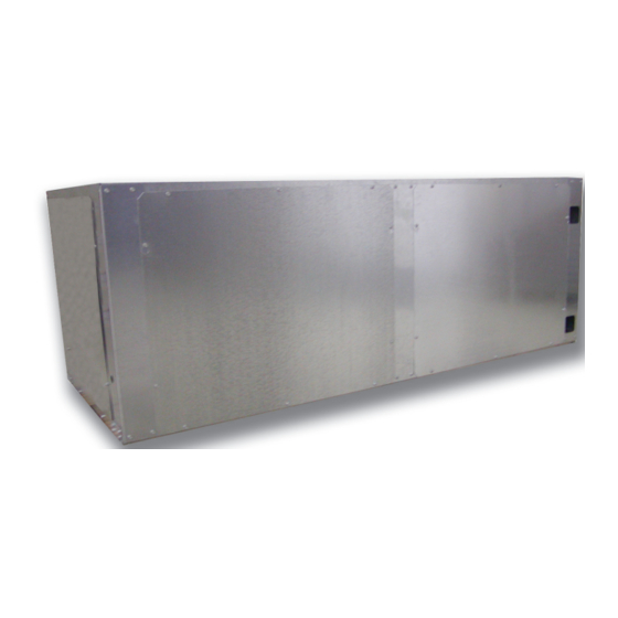
Axiom™ Water-to-Water — EXW
5–20 Tons — 60 Hz
Only qualified personnel should install and service the equipment. The installation, starting up, and servicing of
heating, ventilating, and air-conditioning equipment can be hazardous and requires specific knowledge and training.
Improperly installed, adjusted or altered equipment by an unqualified person could result in death or serious injury.
When working on the equipment, observe all precautions in the literature and on the tags, stickers, and labels that are
attached to the equipment.
March 2020
SAFETY WARNING
WSHP-SVX02C-EN
Advertisement
Table of Contents

Related Manuals for Trane Technologies Axiom EXW


Summary of Contents for Trane Technologies Axiom EXW
- Page 1 Installation, Operation, and Maintenance Water Source Heat Pump Axiom™ Water-to-Water — EXW 5–20 Tons — 60 Hz SAFETY WARNING Only qualified personnel should install and service the equipment. The installation, starting up, and servicing of heating, ventilating, and air-conditioning equipment can be hazardous and requires specific knowledge and training. Improperly installed, adjusted or altered equipment by an unqualified person could result in death or serious injury.
- Page 2 Introduction Read this manual thoroughly before operating or servicing this unit. WARNING Proper Field Wiring and Grounding Warnings, Cautions, and Notices Required! Safety advisories appear throughout this manual as Failure to follow code could result in death or serious required. Your personal safety and the proper operation of injury.
- Page 3 Introduction Copyright WARNING This document and the information in it are the property of Personal Protective Equipment (PPE) Trane, and may not be used or reproduced in whole or in Required! part without written permission. Trane reserves the right to revise this publication at any time, and to make changes Failure to wear proper PPE for the job being undertaken could result in death or serious injury.
-
Page 4: Table Of Contents
Table of Contents General Information ..... 5 Jobsite Inspection ....5 Jobsite Storage . -
Page 5: General Information
General Information • Cover the unit(s) with a waterproof tarp to protect them from the elements. WARNING • Make provisions for continuous venting of the covered Fiberglass Wool! units to prevent moisture from standing on the unit(s) Product contains fiberglass wool. Disturbing the surfaces. - Page 6 General Information Deluxe 24V Controls The Deluxe 24V control design will incorporate a microprocessor-based control board. The Trane microprocessor board is factory wired to a terminal strip to provide all necessary terminals for field connection. The deluxe board is equipped with a random start relay, anti- short cycle timer, brown out protection, compressor disable, unit safety control, diagnostics and a generic relay (which may be available for field use).
-
Page 7: Model Number Description
Model Number Description Digits 1-3: Unit Configuration EXW = Water to Water Heat Pump Digit 4: Development Sequence E = R-410A Digits 5-7: Nominal Size (Tons) 060 = 5 Tons 120 = 10 Tons 240 = 20 Tons Digit 8: Voltage (Volts/Hz/Phase) 1 = 208/60/1 2 = 230/60/1 3 = 208/60/3... -
Page 8: Dimensions And Clearances
Dimensions and Clearances WARNING Improper Unit Lift! Test lift unit approximately 24 inches to verify proper center of gravity lift point. To avoid dropping of unit, reposition lifting point if unit is not level. Failure to properly lift unit could result in death or serious injury or possible equipment or property-only damage. - Page 9 Dimensions and Clearances Figure 2. EXWE060 WSHP-SVX02C-EN...
- Page 10 Dimensions and Clearances Figure 3. EXWE120 WSHP-SVX02C-EN...
- Page 11 Dimensions and Clearances Figure 4. EXWE240 WSHP-SVX02C-EN...
-
Page 12: Installation
Installation General Installation Checks WARNING The checklist below is a summary of the steps required to Improper Unit Lift! successfully install a unit. This checklist is intended to acquaint the installing personnel with procedures Test lift unit approximately 24 inches to verify proper required in the installation process. -
Page 13: Cleaning And Flushing The Water Loop
Installation Figure 5. Water connection Cleaning and Flushing the Water Loop water being dumped). Continue blow down until the water leaving the drain runs clear, but not less than 2 After the piping system is complete, the flexible hose hours. connectors should be doubled back to complete the water 6. -
Page 14: Using Antifreeze
Installation Using Antifreeze Field Installed Power Wiring In areas of the country where entering water temperatures drop below 45°F or where piping is being run through WARNING areas subject to freezing, the loop must be freeze protected Hazardous Voltage! by using an approved antifreeze solution to prevent the earth loop water from freezing inside the heat exchanger. -
Page 15: Control Power Transformer
Installation Controls Using 24 VAC Figure 7. Unit power wiring Before installing any wire, refer to the electrical access UNIT POWER WIRING locations on the unit dimensions starting on page 3 PHASE POWER SUPPLY • Ensure that the AC control wiring between the controls 1TB1 and the unit’s termination point does not exceed three (3) ohms/conductor for the length of the run. -
Page 16: Electrical
Electrical Table 6. Electrical performance EXWE units Maximum Minimum Maximum Minimum Overcurrent VOLTS-AC/ Utilization Utilization Total Unit Comp Comp No. of Circuit Protective Model No. HZ/PH Voltage Voltage RLA (ea) LRA (ea) Compres. Ampacity Device 208/60/1 27.6 27.6 158.0 34.5 230/60/1 27.6 27.6... -
Page 17: Pre-Start
Pre-Start Pre-Start-up Checklist Before energizing the unit, the following system devices must be checked: – Is the high voltage power supply correct and in accordance with the nameplate ratings? – Is the field wiring and circuit protection the correct size? –... -
Page 18: Unit Start-Up
Unit Start-Up Start-up with the system controls is included below: 1. Set the system control to the cooling mode of operation. 2. Turn on the circulation pumps. The compressor should NOT run. 3. Reduce the temperature control setting until the compressor, reversing valve and solenoid valve are energized. -
Page 19: Operating Data
Operating Data Table 7. Operating data for cooling EXWE060 Source Load Compressor Water Suction Flow Temp Rise Water Temp Pressure Discharge Unit Model EWT °F WPD FT °F EWT °F Flow GPM WPD FT Drop °F PSIG Pressure PSIG 10.0 12 - 16 10.0 10 - 13... - Page 20 Operating Data Table 8. Operating data for heating EWXE060 Source Load Compressor Water Suction Discharge Flow Temp Drop Flow Water Temp Pressure Pressure Unit Model EWT °F WPD FT °F EWT °F WPD FT Rise °F PSIG PSIG 10.0 10 - 13 10.0 12 - 15 86 - 99...
- Page 21 Operating Data Table 9. Operating data for cooling EWXE120 Source Load Compressor Water Water Discharge Temp Rise Flow Temp Drop Suction Pressure Unit Model EWT °F Flow GPM WPD FT EWT °F WPD FT °F Pressure PSIG PSIG 10.0 23 - 30 10.0 21 - 27 95 - 109...
- Page 22 Operating Data Table 10. Operating data for heating EXWE120 Source Load Compressor Water Suction Discharge Water Temp Flow Temp Rise Pressure Pressure Unit Model EWT °F Flow GPM WPD FT Drop °F °F WPD FT °F PSIG PSIG 10.0 21 - 27 10.0 23 - 30 85 - 98...
- Page 23 Operating Data Table 11. Operating data for cooling EXWE240 Source Load Compressor Water Water Suction Flow Temp Rise Temp Pressure Discharge Unit Model °F WPD FT °F EWT °F Flow GPM WPD FT Drop°F PSIG Pressure PSIG 10.0 47 - 60 40.0 10 - 13 91 - 105...
- Page 24 Operating Data Table 12. Operating data for heating EWXE240 Source Load Compressor Suction Water Temp Flow Water Temp Pressure Discharge Unit Model EWT °F Flow GPM WPD FT Drop °F °F Rise °F PSIG Pressure PSIG 10.0 36 - 45 40.0 11 - 14 84 - 97...
-
Page 25: Start-Up Checklist And Log
Operating Data Start-up Checklist and Log In order to minimize troubleshooting and costly system failures, complete the following checks and data entries before the system is put into full operation. Job Name: Model Number: Date: Serial Number: Installing Contractor: Use this form to thoroughly check-out the system and units before and during start-up. -
Page 26: Maintenance
Maintenance Preventive Maintenance It should be noted that the water quality should be checked periodically. See Table Maintenance on the unit is simplified with the following Table 14. Water quality table preventive suggestions: Scaling WARNING Calcium and magnesium (total hardness) Less than 350 ppm Hazardous Voltage! Corrosion Disconnect all electric power, including remote... -
Page 27: Troubleshooting
Troubleshooting • Verify that the unit is receiving electric supply power. WARNING • Ensure that the fuses in the fused disconnect (field installed) are intact. Hazardous Service Procedures! After completing the preliminary checks, inspect the unit The maintenance and troubleshooting procedures for other obvious problems such as leaking connection, recommended in this manual could result in exposure broken or disconnected wires, etc. - Page 28 Troubleshooting Table 15. Troubleshooting checklist (continued) Problem Heating Cooling Cause Correction Undercharged Locate leak, repair and recharge Low suction pressure Restricted thermal expansion valve Repair / replace Inadequate GPM Increase GPM Inadequate GPM Increase GPM Water too cold Increase temperature Low Pressure switch open Undercharged with refrigerant Increase charge...
-
Page 29: Wiring
Wiring Figure 10. Deluxe 24V - single circuit - single phase WSHP-SVX02C-EN... - Page 30 Wiring Figure 11. Deluxe 24V - dual circuit - three phase WSHP-SVX02C-EN...
-
Page 31: Warranty
Warranty Standard Warranty The standard water-source heat pump warranty is Trane’s parts-only warranty, running 12-months from startup, not to exceed 18-months from shipment. Extended Warranty The optional extended warranty is a second through fifth year warranty. The time starts at the end of standard 1-year coverage through the fifth year. - Page 32 Trane - by Trane Technologies (NYSE: TT), a global climate innovator - creates comfortable, energy efficient indoor environments for commercial and residential applications. For more information, please visit trane.com or tranetechnologies.com. Trane has a policy of continuous product and product data improvement and reserves the right to change design and specifications without notice.
Need help?
Do you have a question about the Axiom EXW and is the answer not in the manual?
Questions and answers