Table of Contents
Advertisement
Quick Links
User manual
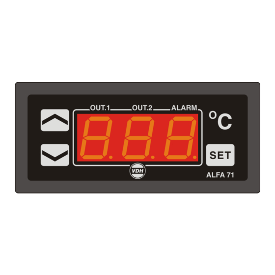
ALFA 71 PI SSR 24Vdc
Thermostat
Open collector Solid State Relay output
VDH doc. 100698
Software: 100801 ALFA71 PI SSR
* Installation.
On the top side of the ALFA 71 PI SSR 24Vdc is shown how the sensors, power supply, relays and
Solid-State output has to be connected. After connecting the ALFA 71 PI SSR 24Vdc to the power
supply, a self test function is started. As this test is finished the measured temperature appears in the
display.
* Control.
The ALFA 71 PI SSR 24Vdc thermostat can be controlled by four pushbuttons on the front.
These keys are:
SET
- view / change the setpoint.
UP
- increase the setpoint.
DOWN
- decrease the setpoint.
C
- hidden push button above the SET key and behind C symbol.
* Viewing setpoint.
By pushing the SET key the setpoint appears in the display. The decimal point of the last display starts
blinking. A few seconds after releasing the SET key the setpoint disappears and the measured
temperature is shown again in the display.
* Changing setpoint.
Push the SET key and the setpoint appears in the display. Release the SET key. Now push the SET
key again together with the UP or DOWN keys to change the setpoint. A few seconds after releasing
the keys the measured temperature shows again in the display.
* Status of the Relays.
By pushing the hidden C key the display shows the status of the relays. Each display segment shows
the status of the relay output, showing 0=off and 1=on. The code 100 means relay 1 is on and relay
2 is off. A few seconds after releasing the keys the measured temperature shows again in the display.
* PI-percentage.
By pushing the UP key the display shows the internal PI-percentage (for P04=2,4) or the status of the
solid state output (for P04=1,3). For the solid state output, 100 means on, 0 means off. A few seconds
after releasing the keys the measured temperature shows again in the display.
* Setting internal parameters.
Next to the adjustment of the setpoint, internal settings can be made like differential, sensor-offset,
setpoint range and the functions of the thermostat.
Push the DOWN key more than 10 seconds, to enter the 'Internal Programming Menu'. In the left
display the upper and lower segment are blinking.
Over the UP and DOWN keys the required parameter can be selected (see table for the parameters).
If the required parameter is selected, the value can be read-out by pushing the SET key.
Pushing the UP or DOWN key to change the value of this parameter.
If after 20 seconds no key is pushed, the ALFA 71 PI SSR 24Vdc changes to the normal operation
mode.
Version: v1.0
File: Do100698.wpd
1
Date: 06-10-2010
Range: -50/+50,0 C
Advertisement
Table of Contents

Related Manuals for VDH Products ALFA 71 PI SSR 24Vdc

Summary of Contents for VDH Products ALFA 71 PI SSR 24Vdc
- Page 1 File: Do100698.wpd * Installation. On the top side of the ALFA 71 PI SSR 24Vdc is shown how the sensors, power supply, relays and Solid-State output has to be connected. After connecting the ALFA 71 PI SSR 24Vdc to the power supply, a self test function is started.
- Page 2 Indicates the Sensor e.g. 2 C to much, the Sensor Offset has to be decreased with 2 C. * Error messages. In the display of the ALFA 71 PI SSR 24Vdc the following error messages can appear: - Minimum alarm.
- Page 3 * Parameters ALFA 71 PI SSR 24Vdc Para- Description Parameter Range Default meter Function Relay 1 1 = Cool 1..3 2 = Heat 3 = Alarm Function Relay 2 1 = Cool 1..3 2 = Heat 3 = Alarm Function Solid-State open collector output 1..4...
- Page 4 * Dimensions. * Connections. * Address. VDH Products BV Tel: +31 (0)50 - 30 28 900 Produktieweg 1 Fax: +31 (0)50 - 30 28 980 9301 ZS Roden Email: info@vdhproducts.nl The Netherlands Internet: www.vdhproducts.nl...
Need help?
Do you have a question about the ALFA 71 PI SSR 24Vdc and is the answer not in the manual?
Questions and answers