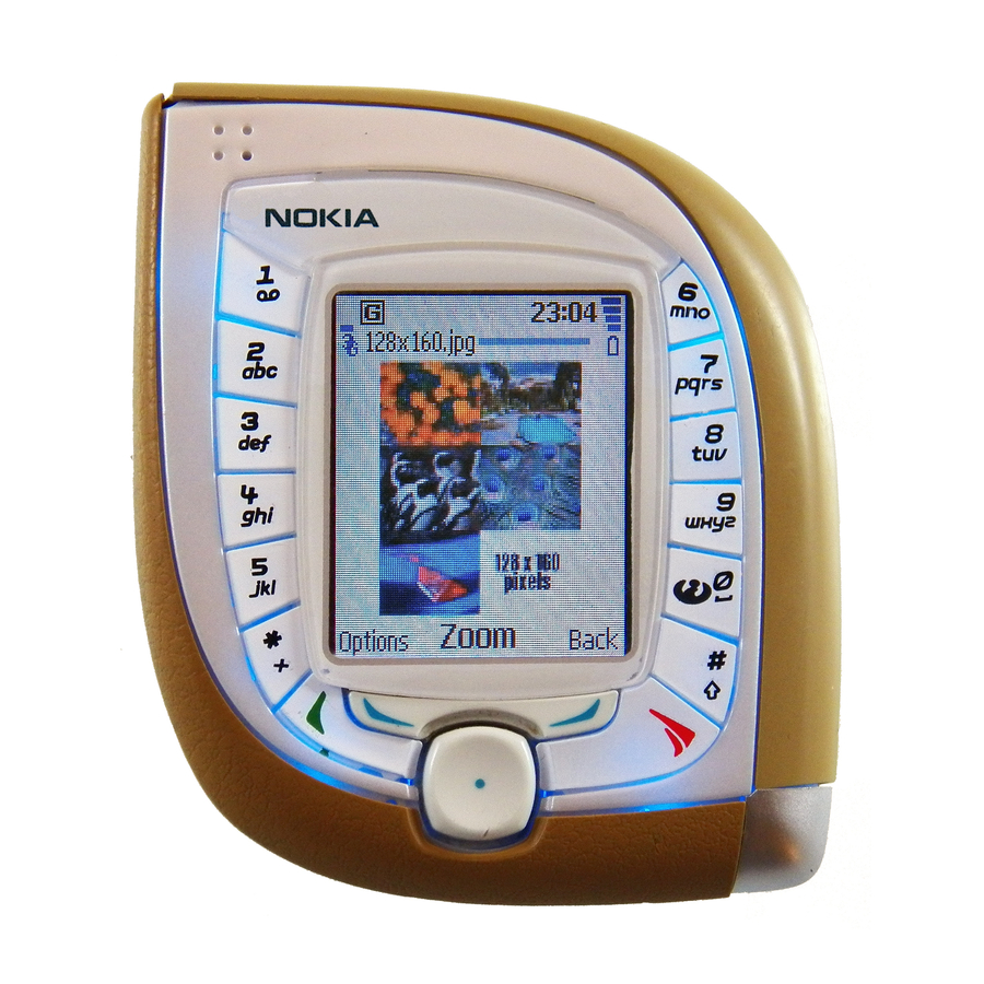
Nokia 7600 Disassembly Instructions Manual
Hide thumbs
Also See for 7600:
- User manual (156 pages) ,
- Troubleshooting manual (32 pages) ,
- Owner's manual (16 pages)
Subscribe to Our Youtube Channel
Summary of Contents for Nokia 7600
- Page 1 Customer Care Solutions NMM-3 Series Cellular Phones 5 - Disassembly Instructions Copyright 2003 Nokia Corporation. Issue 1 (11/2003) Page 5-1 Company Confidential...
-
Page 2: Table Of Contents
Re-assembly Instructions ......................Assembly of B-Cover Module ....................Assemble of UI Module ......................Assembly of the ATO ........................ Assembly of the Transceiver ....................Visual Quality Check during Re-assembly ................Copyright 2003 Nokia Corporation. Page 5-2 Issue 1 (11/2003) Company Confidential... -
Page 3: Disassembly Instructions
5 - Disassembly Instructions Disassembly Instructions 1. First remove LH Sleeve. 2. Now remove RH Sleeve. 3. Dismount C-Cover. 4. Pull up D-cover, which is attached to B-cover with adhesive tape. Copyright 2003 Nokia Corporation. Issue 1 (11/2003) Page 5-3 Company Confidential... - Page 4 8. Loosen the clips anti-clockwise by using the SRT-6 as a lever. Do not twist the SRT-6 because this could cause damage to the cover. Copyright 2003 Nokia Corporation. Page 5-4 Issue 1 (11/2003) Company Confidential...
- Page 5 11. Unlock the three clips from the UI Assembly, as indicated. 12. If unlocking doesn’t work check that the Antenna screw has been removed. Copyright 2003 Nokia Corporation. Issue 1 (11/2003) Page 5-5 Company Confidential...
- Page 6 14. After opening the side clips the Lightguide can be removed. 15. Carefully open LCD Connector with the SRT-6. Do not damage the sensitive flex foil. 16. Remove LCD. Copyright 2003 Nokia Corporation. Page 5-6 Issue 1 (11/2003) Company Confidential...
- Page 7 18. Separate UI PWB from Engine Shield. 19. Dismount Engine module. 20. Use disassembly side of the SRT- 11 to remove the VGA Camera. Use the other side of the SRT-11 for assembly. Copyright 2003 Nokia Corporation. Issue 1 (11/2003) Page 5-7 Company Confidential...
- Page 8 22. Using a charger plug remove the DC Jack. 23. Remove Vibra Motor, taking care not to damage the spring contacts. 24. Unlock the side snaps to remove the IT Window. Copyright 2003 Nokia Corporation. Page 5-8 Issue 1 (11/2003) Company Confidential...
- Page 9 25. Push out the Volume Keys, taking care not to damage the silicon. 26. Remove the Microphone from its guidance. 27. Remove Camera Shutter Key. 28. Remove Power Key. Copyright 2003 Nokia Corporation. Issue 1 (11/2003) Page 5-9 Company Confidential...
- Page 10 30. Press out Rubber Gasket from the outside. 31. There are two plastic clips, which have to be unlocked before removing GSM Antenna. 32. Finally remove HF Speaker with tweezers. Copyright 2003 Nokia Corporation. Page 5-10 Issue 1 (11/2003) Company Confidential...
-
Page 11: Re-Assembly Instructions
B- Cover recesses. Note: Ensure that the annulus of the camera boot is concentric with the B- Cover camera annulus. Copyright 2003 Nokia Corporation. Issue 1 (11/2003) Page 5-11 Company Confidential... - Page 12 Note: Ensure the front and back of the window is not cosmetically dam- aged by wearing soft gloves when pressure is applied to the window. Copyright 2003 Nokia Corporation. Page 5-12 Issue 1 (11/2003) Company Confidential...
- Page 13 Note: Ensure the contacts on each device are avoided and the DC Jack snapped home. 9 (ii). Removing the microphone. (ii) Copyright 2003 Nokia Corporation. Issue 1 (11/2003) Page 5-13 Company Confidential...
-
Page 14: Assemble Of Ui Module
Note: Ensure the metal body of the earpiece is not distorted and the con- tacts are not deformed. Ensure the earpiece is fully assembled into the LCD frame. Copyright 2003 Nokia Corporation. Page 5-14 Issue 1 (11/2003) Company Confidential... - Page 15 The connector should snap into place. Note: The connector must be assem- bled keeping it flat and applying even pressure across the top of the rigi- diser. Copyright 2003 Nokia Corporation. Issue 1 (11/2003) Page 5-15 Company Confidential...
-
Page 16: Assembly Of The Ato
Note: Ensure the board to board con- nector and camera assembly are avoided by only holding the PWB module in the designated areas indi- cated. Protection Pad (not supplied) Copyright 2003 Nokia Corporation. Page 5-16 Issue 1 (11/2003) Company Confidential... - Page 17 Note: Ensure pressure is only applied directly above the clips. Protection Pad (not supplied) Copyright 2003 Nokia Corporation. Issue 1 (11/2003) Page 5-17 Company Confidential...
-
Page 18: Assembly Of The Transceiver
Make sure the blind clip over the sys- tem connector (9) is also assembled. Note 2: Make sure the LCD protective tape is removed before assembly of A-Cover module. Copyright 2003 Nokia Corporation. Page 5-18 Issue 1 (11/2003) Company Confidential... - Page 19 D-Cover once assembled to ensure the adhesive takes. Ensure gloves are used and the cosmetic Class I painted surface of the D-Cover is not dam- aged or contaminated in any way. Copyright 2003 Nokia Corporation. Issue 1 (11/2003) Page 5-19 Company Confidential...
-
Page 20: Visual Quality Check During Re-Assembly
• Ensure there is no contamination or damage in the B-Cover battery bay area • Ensure the LCD protective tape and D-Cover adhesive backing tapes have been removed • Ensure the phone is free from dust or hairs Copyright 2003 Nokia Corporation. Page 5-20 Issue 1 (11/2003) Company Confidential...


Need help?
Do you have a question about the 7600 and is the answer not in the manual?
Questions and answers