Advertisement
Available languages
Available languages
Quick Links
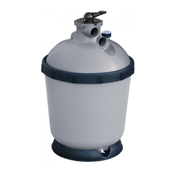
MAGIC TOP INJECTÉ
MTi-400
MTi-400EH
MTi-500
FILTRE À SABLE POUR PISCINE
Français: page 1 - English: page 9 - Deutch: Seite 17
NOTICE D'INSTALLATION ET CONSEILS D'UTILISATION
A lire attentivement et à conserver pour consultation ultérieure.
2014/04 - Indice de révision : F - Code : 0026650
1/24
Advertisement

Related Manuals for Procopi Aquareva MTi-400


Summary of Contents for Procopi Aquareva MTi-400
- Page 1 MAGIC TOP INJECTÉ MTi-400 MTi-400EH MTi-500 FILTRE À SABLE POUR PISCINE Français: page 1 - English: page 9 - Deutch: Seite 17 NOTICE D’INSTALLATION ET CONSEILS D’UTILISATION A lire attentivement et à conserver pour consultation ultérieure. 2014/04 - Indice de révision : F - Code : 0026650 1/24...
- Page 2 CONTENU 1 Anneau ceinture 1 Tube plongeur 1 couvercle 1 Cuve 1 Joint torique de couvercle et son bouchon avec vanne multivoies 1 Bouchon de vidange 1 Diffuseur 1 Plancher crépiné 1 Manomètre + joint et écrou avec joint torique 1 Raccord transparent 2 Raccords noirs 50x38 2 Raccords gris 50x45...
- Page 3 CHARGEMENT•DU•FILTRE Retirer l’ensemble couvercle/vanne. Celui-ci est Dévisser et retirer l’anneau ceinture. posé à l’envers pour le transport. Visser le bouchon de vidange. Collage des raccords sur le couvercle : Le raccord transparent côté sortie “égout”, les raccords noirs ou gris côtés “entrée” et sortie “pompe”.
- Page 4 Orienter le manomètre et le placer dans son Montage du manomètre : logement. Mettre le joint par le dessus dans le logement du couvercle. Mise en place du diffuseur : Par le dessous du couvercle, visser l’écrou Centrer le diffuseur dans le logement, et le laiton à...
- Page 5 INSTRUCTIONS POUR LA MISE EN PLACE DU COUVERCLE Présenter le couvercle au dessus de la cuve. Enfoncer le couvercle dans la cuve en un point. Conserver l’appui sur ce point à l’aide du genou. Positionner les deux mains de façon qu’elles Pousser simultanément sur les deux mains forment avec le genou, 3 points répartis à...
- Page 6 Connecter le filtre à la pompe et à la Liaison pompe/filtre piscine aspiration Vidange refoulement en respectant le schéma de principe ci-contre. Les raccords cannelés possèdent un bossage servant butée à l’emmanchement des tuyaux. raccord vidange étant Sortie eau filtrée transparent, la partie restant visible servira de voyant de turbidité.
- Page 7 CONSEILS D’UTILISATION IMPORTANT : Lors de la première mise en service du filtre, bien observer le sens de circulation de l’eau : en position “Filtration”, l’eau doit traverser le filtre de haut en bas. Si les tuyauteries ont été inversées au montage, ou si la vanne multivoies présente un défaut, l’eau va traverser le filtre de bas en haut, et il en résultera obligatoirement et très rapidement une détérioration de la cuve et des crépines.
- Page 8 MAGIC TOP INJECTED S. A au capital de 7 000 000 € - R.C.S/Rennes B 333 263 846 000 37 2014/04 - Indice de révision : F - Code : 0026650 8/24...
- Page 9 MAGIC TOP INJECTED MTi-400 MTi-400EH MTi-500 SAND FILTER FOR SWIMMING POOLS INSTALLATION AND OPERATING INSTRUCTIONS To be read carefully and kept for future reference 2014/04 - Indice de révision : F - Code : 0026650 9/24...
- Page 10 CONTENT 1 Ring 1 Collector pipe with plug 1 Filter tank 1 Lid o-ring 1 lid with multiport valve 1 Diffuser 1 collector plate 1 Pressure gauge w/seal+nut 1 Drain plug with o-ring 1 Transparent union 2 Black unions, 50x38 2 Unions, grey, 50x45 1 Tube of PVC glue 3 TORRO collar clamps...
- Page 11 LOADING THE FILTER MEDIA Remove the lid/valve assembly (positioned Unscrew and remove the ring. upside-down during transport). Screw in the drain plug. Glueing the unions to the lid: The transparent union to the "waste" outlet, the black or grey unions to the pump inlet and outlet. Caution: avoid using excess glue, this could dammage the valve Carefully pour the sand into the filter and,...
- Page 12 Position the pressure gauge correctly and Installing the pressure gauge: place it in its housing. Place the o-ring in its groove in the cover. Mounting the diffuser: Working from underneath the cover, tighten the Centre the diffuser in its housing, and push it bronze nut by hand, then moderately using a firmly against the lid, twist it to slide the tongue 22 tube wrench.
- Page 13 INSTRUCTIONS FOR POSITIONING AND CLOSING THE LID Hold the lid over the filter tank. Press the lid into the filter tank at one point. Using your knee, maintain pressure on this point. Position your two hands on the lid such that Bear down simultaneously with both hands to they are equidistant both from each other push the lid completely into the filter tank.
- Page 14 Connect the filter to the pump and Pump/ filter connection pool suction and returns according to Drain the diagram opposite. Push the tubes onto the barbed unions until they reach the boss (bump) marking the stop point. The drain union is transparent, the clear section can thus act as a sight Filtered water outlet glass to assess turbidity.
- Page 15 RECOMMENDATIONS IMPORTANT: Upon putting the filter into operation for the first time observe the direction of water flow attentively: in “Filtration” position, water should flow from the top of the filter to the bottom. In the event that the pipes were inverted during assembly or that the multiport valve is faulty, water will travel from the bottom to the top leading swiftly and inevitably to damage to the collector plate and the walls of the tank.
- Page 16 PLC with a share capital of €7 ,000 ,000 2014/04 - Indice de révision : F - Code : 0026650 16/24 Register of commerce/Rennes B 333 263 846 000 37...
- Page 17 MAGIC TOP INJECTED MTi-400 MTi-400EH MTi-500 SANDFILTER FÜR SCHWIMMBÄDER MONTAGE- UND BEDIENUNGSANLEITUNG Lesen Sie sie sorgfältig durch und verwahren Sie sie an einem sicheren Platz. 2014/04 - Indice de révision : F - Code : 0026650 17/24...
- Page 18 BESTANDTEILE 1 Dichtring 1 Sammelrohr mit Stopfen 1 Deckel 1 Filtertank 1 Deckel-O-Ring 1 Entleerungsstopfen mit 1 Diffusor 1 Siebfilterboden 1 Manometer m. Dichtung+Mutter O-Ring 2 Schwarze, Anschlüsse 1 Transparenter Anschluss 2 Grau, Anschlüsse 50x45 1 Tube PVC-Kleber 50x38 3 Befestigungsschellen TORRO Artikelbezeichnung Max.
- Page 19 EINFÜLLUNG DER FILTERMEDIEN Entfernen Sie die Baugruppe Deckel/Ventil. Lösen und entfernen Sie den Dichtring. (Diese Baugruppe wird umgedreht transportiert.) Schrauben Sie den Entleerungsstopfen an. Kleben Sie die Anschlüsse auf den Deckel – den transparenten Anschluss auf den Abwasser- Ausgang und die schwarzen Anschlüsse auf den Pumpen-Ein- und Ausgang.
- Page 20 Richten Sie das Manometer korrekt aus und Montage des Manometers: legen Sie es sein Gehäuse. Legen Sie den O-Ring in die dafür vorgesehene Nut im Deckel ein. Montage des Diffusors: Ziehen Sie die Bronzemutter unterhalb der Positionieren Sie den Diffusor unterhalb seines Abdeckung zuerst mit der Hand, anschließend Gehäuses, schieben Sie ihn gegen den Deckel vorsichtig mit einem Rohrschlüssel (22 mm)
- Page 21 ANWEISUNGEN FÜR DIE MONTAGE DES DECKELS Halten Sie den Deckel über den Tank. Drücken Sie den Deckel an einem Punkt auf den Filtertank. Halten Sie den Druck an diesem Punkt mithilfe Ihres Knies aufrecht. Legen Sie die Hände auf den Deckel, Drücken Sie den Deckel mit beiden Händen sodass sie gleich weit voneinander und von gleichzeitig auf den Filtertank.
- Page 22 Verbinden Sie den Filter mit Pumpe, Verbindung Pumpe/Filter Wassereintritt- -ablauf, Entleerung entsprechend dem nebenstehenden Diagramm. Drücken Sie die Rohre in die gerippten Anschlüsse bis zur Nabe (Erhebung), welche den Arretierpunkt markiert. Der Entleerungs-Anschluss Gefilterter Wasserablauf transparent, sodass Kontrollfenster für die Feststellung von Trübungen dient.
- Page 23 EMPFEHLUNGEN ACHTUNG! Bei der ersten Inbetriebnahme des Filters muss die Flussrichtung des Wassers sorgfältig überwacht werden: in der Position FILTRATION muss das Wasser von oben nach unten fließen. Falls die Rohre umgekehrt eingebaut wurden oder das Mehrwegeventil defekt ist, fließt das Wasser von unten nach oben. Das führt schnell und unvermeidbar zu einer Schädigung des Filterbodens und der Tankwände.
- Page 24 2014/04 - Indice de révision : F - Code : 0026650 24/24...
Need help?
Do you have a question about the Aquareva MTi-400 and is the answer not in the manual?
Questions and answers