Table of Contents
Advertisement
Quick Links
CALIBRATION PROCEDURE
NI 9218
2-Channel, 24-Bit, Universal Analog Input Module
This document contains information for calibrating the National Instruments 9218. For more
information on calibration, visit
Contents
Software.................................................................................................................................... 1
Documentation.......................................................................................................................... 2
Test Equipment......................................................................................................................... 3
Test Conditions......................................................................................................................... 4
Initial Setup............................................................................................................................... 5
Verification............................................................................................................................... 5
Current Accuracy Verification, 20 mA mode .................................................................. 6
Voltage Accuracy Verification, 60 V mode ..................................................................... 7
Voltage Accuracy Verification, 16 V mode ..................................................................... 9
Voltage Accuracy Verification, 65 mV mode .................................................................. 10
Voltage Accuracy Verification, IEPE 5 V mode.............................................................. 12
Bridge Accuracy Verification, 22 mV/V mode................................................................ 14
Adjustment................................................................................................................................ 17
Voltage Accuracy Adjustment, 16 V mode...................................................................... 17
Voltage Accuracy Adjustment, 60 V mode...................................................................... 18
Voltage Accuracy Adjustment, 65 mV mode................................................................... 19
Current Accuracy Adjustment, 20 mA mode ................................................................... 20
Voltage Accuracy Adjustment, IEPE 5 V mode .............................................................. 20
Bridge Accuracy Adjustment, 22 mV/V mode ................................................................ 21
EEPROM Update ..................................................................................................................... 23
Reverification ........................................................................................................................... 23
Accuracy Under Calibration Conditions .................................................................................. 23
Worldwide Support and Services ............................................................................................. 24
Pinout Signals ........................................................................................................................... 25
Software
Calibrating the NI 9218 requires the installation of NI-DAQmx 15.1or later on the calibration
system. You can download NI-DAQmx from
LabVIEW, LabWindows
NI-DAQmx you only need to install support for the application software that you intend to use.
ni.com/calibration
™
™
/CVI
, C/C++, C#, and Visual Basic .NET. When you install
.
ni.com/downloads
. NI-DAQmx supports
Advertisement
Table of Contents

Related Manuals for National Instruments 9218


Summary of Contents for National Instruments 9218
-
Page 1: Table Of Contents
Accuracy Under Calibration Conditions .................. 23 Worldwide Support and Services ..................... 24 Pinout Signals ........................... 25 Software Calibrating the NI 9218 requires the installation of NI-DAQmx 15.1or later on the calibration system. You can download NI-DAQmx from . NI-DAQmx supports ni.com/downloads ™... -
Page 2: Documentation
Documentation Consult the following documents for information about the NI 9218, NI-DAQmx, and your application software. All documents are available on and help files install with the ni.com software. NI cDAQ-9174/9178 USB Chassis Quick Start NI-DAQmx installation and hardware setup... -
Page 3: Test Equipment
<3.5 V. ±22 mV/V ±22 mV/V For DMM2, use a second mode mode DMM with <50 ppm gain error, and <2 µV of offset error at voltages <50 mV. NI 9218 Calibration Procedure | © National Instruments | 3... -
Page 4: Test Conditions
• Keep relative humidity below 80%. • Allow a warm-up time of at least 10 minutes to ensure that the NI 9218 measurement circuitry is at a stable operating temperature. • Only one of each NI 9982, NI 9983, and NI 9987 is sufficient for this calibration procedure. -
Page 5: Initial Setup
This section provides instructions for verifying the NI 9218 specifications. The following performance verification procedures describe the sequence of operations and test points required to verify the NI 9218 and assumes that adequate traceable uncertainties are available for the calibration references. -
Page 6: Current Accuracy Verification, 20 Ma Mode
Current Accuracy Verification, 20 mA mode Complete the following procedure to determine the As-Found status of the NI 9218. Set the calibrator to Standby mode (STBY). Connect the NI 9218 to the calibrator as shown in Figure 1. Figure 1. Current Accuracy Verification Connections AI–... -
Page 7: Voltage Accuracy Verification, 60 V Mode
10. Disconnect the calibrator from the NI 9218. Voltage Accuracy Verification, 60 V mode Complete the following procedure to determine the As-Found status of the NI 9218. Set the calibrator to Standby mode (STBY). Connect the NI 9218 to the calibrator as shown in Figure 2. - Page 8 Acquire and average samples. Create an AI voltage task on the NI 9218 according to Table 5. Table 5. NI 9218 Configuration for Accuracy Verification Min (V) Max (V) Scaled Units Channel Configuration Volts DC Coupled Configure the AI voltage task timing according to Table 6.
-
Page 9: Voltage Accuracy Verification, 16 V Mode
Voltage Accuracy Verification, 16 V mode Complete the following procedure to determine the As-Found status of the NI 9218. Set the calibrator to Standby mode (STBY). Connect the NI 9218 to the calibrator as shown in Figure 3. Figure 3. Voltage Accuracy Verification Connections CH 0 AI–/EX–... -
Page 10: Voltage Accuracy Verification, 65 Mv Mode
10. Disconnect the calibrator from the device. Voltage Accuracy Verification, 65 mV mode Complete the following procedure to determine the As-Found status of the NI 9218. Set the calibrator to Standby mode (STBY). Connect the NI 9218 to the calibrator as shown in Figure 4. - Page 11 Acquire and average samples. Create an AI voltage task on the NI 9218 according to Table 11. Table 11. NI 9218 Configuration for Accuracy Verification Min (mV) Max (mV) Scaled Units Channel Configuration Volts DC Coupled Configure the AI voltage task timing according to Table 12.
-
Page 12: Voltage Accuracy Verification, Iepe 5 V Mode
Voltage Accuracy Verification, IEPE 5 V mode Complete the following procedure to determine the As-Found status of the NI 9218. Connect the NI 9218 to the calibrator as shown in Figure 5. Figure 5. Voltage Accuracy Verification Connections CH 0 AI–... - Page 13 512 k 51.2 Set the calibrator to Operate mode (OPR). Commit the task using DAQmx Control Task Function/VI. Wait 6 seconds for the AC coupling filter on the NI 9218 to settle before Note acquiring samples. Start the task. Calculate and record the AC magnitude for each channel on the NI 9218.
-
Page 14: Bridge Accuracy Verification, 22 Mv/V Mode
Complete the following steps to verify the full-bridge accuracy of an NI 9218. Connect a resistor network to the NI 9218 and two DMMs as shown in Figures 6, 7, or 8 for the appropriate test point value indicated in Table 17. Observe the following conditions when connecting the equipment to the NI 9218. - Page 15 Enable autozero on DMM1. Configure DMM2 for a voltage measurement in the 100 mV range. Enable autozero on DMM2. Configure the NI 9218 for the NI 9982 measurement adapters using MAX. NI 9218 Calibration Procedure | © National Instruments | 15...
- Page 16 Acquire and average samples. Create an AI bridge with excitation task on the NI 9218 according to Table 18. Table 18. NI 9218 Configuration for Accuracy Verification Channel Excitation Excitation Bridge (V/V) (V/V) Configuration Value (V) Source Configuration -0.022 0.022...
-
Page 17: Adjustment
NI 9218. Voltage Accuracy Adjustment, 16 V mode Complete the following procedure to adjust the accuracy performance of the NI 9218. Set the calibrator to Standby mode (STBY). Connect the NI 9218 to the calibrator as shown in Figure 3. -
Page 18: Voltage Accuracy Adjustment, 60 V Mode
Repeat steps c through j for each channel. Disconnect the NI 9218 from the calibrator. Voltage Accuracy Adjustment, 60 V mode Complete the following procedure to adjust the accuracy performance of the NI 9218. Voltage Accuracy Adjustment, 16 V mode You must complete the section before starting this section. -
Page 19: Voltage Accuracy Adjustment, 65 Mv Mode
Disconnect the DMM from the NI 9218. Voltage Accuracy Adjustment, 65 mV mode Complete the following procedure to adjust the accuracy performance of the NI 9218. Set the calibrator to Standby mode (STBY). Connect the NI 9218 to the calibrator as shown in Figure 4. -
Page 20: Current Accuracy Adjustment, 20 Ma Mode
Repeat steps c through j for each channel. Disconnect the NI 9218 from the calibrator. Current Accuracy Adjustment, 20 mA mode Complete the following procedure to adjust the accuracy performance of the NI 9218. Voltage Accuracy Adjustment, 65 mV mode You must complete the section before starting this section. -
Page 21: Bridge Accuracy Adjustment, 22 Mv/V Mode
Bridge Accuracy Adjustment, 22 mV/V mode Complete the following steps to adjust the full-bridge accuracy of the NI 9218. Connect the NI 9218 and DMMs to the resistor network as shown in Figures 6, 7, or 8 depending on the test point. - Page 22 Configure DMM2 for a voltage measurement in the 100 mV range. Enable autozero on DMM2. Call the DAQmx Get 9218 Calibration Adjustment Points function to obtain an array of recommended calibration points for the NI 9218. The adjustment points can be achieved by observing the following conditions.
-
Page 23: Eeprom Update
EEPROM Update When an adjustment procedure is completed, the NI 9218 internal calibration memory (EEPROM) is immediately updated. If you do not want to perform an adjustment, you can update the calibration date and onboard calibration temperature without making any adjustments by initializing an external calibration, setting the C Series calibration temperature, and closing the external calibration. -
Page 24: Worldwide Support And Services
National Instruments corporate headquarters is located at 11500 North Mopac Expressway, Austin, Texas, 78759-3504. National Instruments also has offices located around the world. For telephone support in the United States, create your service request at or dial ni.com/support... -
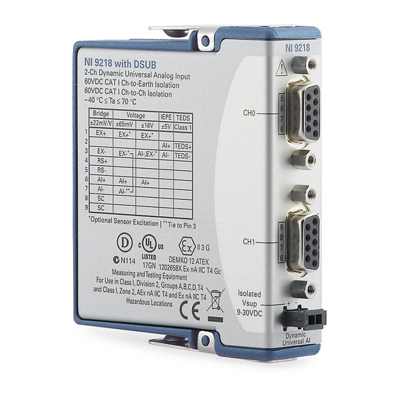
Page 25: Pinout Signals
Pinout Signals Figure 10. NI 9218 with DSUB Pinout and Pin Assignments DSUB PINOUT PIN ASSIGNMENT BY MODE Full-Bridge ±65 mV ±16 V IEPE TEDS — — — — — EX– EX– AI–, EX– AI– T– — — — —... - Page 26 For patents covering NI products/technology, refer to the appropriate location: Help»Patents in your software, the patents.txt file on your media, or the National Instruments Patents Notice at ni.com/patents. You can find information about end-user license agreements (EULAs) and third-party legal notices in the readme file for your NI product.
Need help?
Do you have a question about the 9218 and is the answer not in the manual?
Questions and answers