Table of Contents
Advertisement
Quick Links
Advertisement
Table of Contents

Related Manuals for ATT Hammer Jet v1


Summary of Contents for ATT Hammer Jet v1
- Page 1 Operating Manual Hammer Jet v1 Dryer & Cleaner Revision 1 - April 2020...
-
Page 2: Table Of Contents
EU Declaration of Conformity..................3 Annex 1 to EU Declaration of Conformity ................4 Nameplate ........................5 Safety Instructions ....................... 7 Obligations........................7 Hazard and danger zones ....................8 Intended use ......................8 Misuse ........................9 Disclaimer ........................ 10 Introduction......................10 Hammer Jet Dryer & Cleaner ..................10 Product Overview ....................... -
Page 3: Eu Declaration Of Conformity
EU Declaration of Conformity The undersigned, representing the following manufacturer: Applied Turbine Technology ApS Østager 2, 6400 Sønderborg, Denmark hereby declares that: Machine type no. 10000-40-80 is in conformity with all relevant provisions of the following EC directive(s): DIRECTIVE 2006/42/EC OF THE EUROPEAN PARLIAMENT AND OF THE COUNCIL of 17 May 2006 on machinery The EMC Directive 2004/108/EC Person authorized to collect technical data and make them available to the relevant authorities:... -
Page 4: Annex 1 To Eu Declaration Of Conformity
Annex 1 to EU Declaration of Conformity References to standards and specifications used for the Declaration of Conformity: Harmonized standards: Number Version Title Safety of machinery – Electrical equipment of machines DS/EN 60204- 2006 – General requirements Safety of machinery – Safety-related parts of control DS/EN ISO 13849-1 2006 systems –... -
Page 5: Nameplate
Nameplate The Hammer Jet is provided with a name plate according to the requirements stated in the Directive 2006/42/EC placed on the “End Blinder” plate next to the charging port. The nameplate is showing the CE and EAC (Russia) symbol as well as the website of the manufacturing company (for contact information etc). - Page 6 In the United States hearing protection is by law assigned a single number rating, NRR, which is an abbreviation for a Noise Reduction Rating. Hearing protection is available with NRR ratings from 0 to 30. The required NRR level of a hearing protection is an estimate of the exposed daily noise level dose, which then can be converted to an 8-hour Time Weighed Average called TWA.
-
Page 7: Safety Instructions
Safety Instructions Obligations Obligations of the Operator/manager: The Hammer Jet must only be operated by personnel with the following knowledge: Are aware of the basic workplace safety information and accident prevention regulations. Have been instructed and trained in working with the Hammer Jet. Have read and understood this operating manual. -
Page 8: Hazard And Danger Zones
Hazard and danger zones The hazard and danger zones are illustrated in the above figure. Each hazard zone requires its own protection measures: The NOISE zone requires protection to avoid loss of hearing ability. The EXHAUST zone, where the use of safety glasses are required. The HEATING zone, where use of safety shoes are required. -
Page 9: Misuse
During turbine operation, always ensure that the outlet air from the nozzle opening freely can get out. Do not cover and do not put the nozzle opening in such way that it the air flow is hindered. Misuse The product Hammer Jet should not be used indoor, since the jet turbine is using fuel and the exhaust emission could be toxic. -
Page 10: Disclaimer
ATTENTION Important information A usage situation of a technical nature or similar that is very important. INFORMATION The product without operational disturbances. Provides useful tips and recommendations as well as information about the efficient use. Disclaimer All specifications and instructions in this document conform to the rules and provisions in the EU Machinery Directive 2006/42/EC and Directive 2004/104/EC. -
Page 11: Product Overview
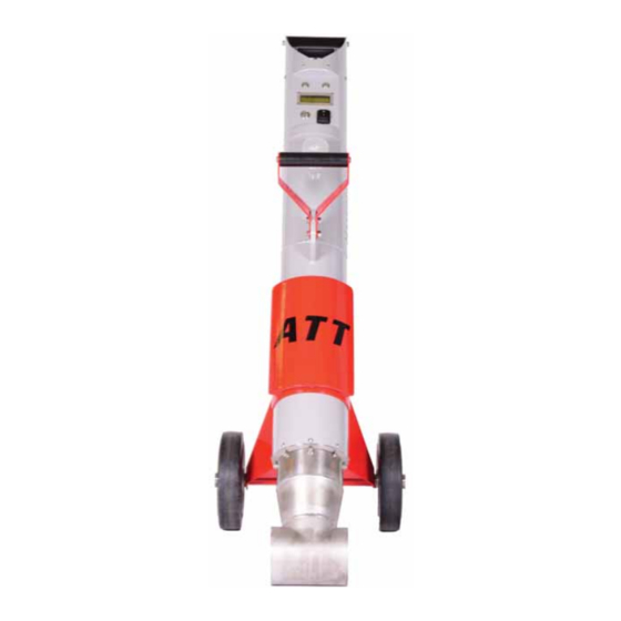
• The Hammer Jet is equipped with a gas turbine which operates on standard diesel type EN590 mixed with 5% ATT turbine oil. The Hammer Jet does not use LPG, which makes its use possible also in populated areas. • Only hot air - no open flames (a requirement for operations many airports etc.) •... -
Page 12: Display "Operation Hours & Time To Service
Display “Operation Hours & Time to Service” - This information appears app. 1 second after activation of the display button with a duration of app. 2 seconds. 1) Total Operating hours and minutes on the installed turbine module 2) Next service time in hours and minutes for the installed turbine module Figure 1 Display “Ready to Start”... -
Page 13: Display "Idle" - Ready To Use
Display “Idle” – Ready to use - This information appears app. 10-15 seconds after activation of the start button. 1) Nozzle air temperature 2) Battery voltage (Must be higher than 11.2V before start-up) 3) Power output 4) Throttle set point Figure 3 - Display Display “Low Power Setting”... -
Page 14: Recommended Elevation For Optimal Drying Speed
Display “High Power Setting” 5) Nozzle air temperature 6) Battery voltage (Must be higher than 11.2V before start-up) 7) Power output 8) Throttle set point Figure 5 - Display Recommended elevation for optimal drying speed Keep the nozzle opening 1-2 cm above the surface to get optimal drying speed. -
Page 15: Accessories And Spares
Turbine incl. Flange and A50H v1 Hammer Jet Turbine nozzle (must be complete 12000-100 Module (HS 8411810090) when returned for service) Hammer Jet v1 Chassis stand-alone Hammer Jet v1 without the 10000-40-80-1 (HS 8411810090) turbine module Protection box for daily use,... -
Page 16: Operation
Use Exxsol D80 or Shellsol D70 petroleum/Kerosene along with 3 % ATT Turbine oil (7000-80) in the mixing ratio 1 to 30. (20 litres of fuel to 0.6 litre of ATT Turbine oil). When utilizing US Gallons, the mixing ratio is 0.6 litre ATT Turbine Oil to 5 US Gallons of... -
Page 17: Before Start-Up
Do not transport or store the Hammer Jet before it has cooled down completely (nozzle temperature must be below 50°C/122°F. Only use the dedicated Hammer Jet Transport Box, when not in use, and for storing and transportation the Hammer Jet. This will shelf the product against dents, dust and dirt. Always keep the Hammer Jet Transport Box clean and tidy. -
Page 18: Safety Stop
1) Prior to start-up, ensure proper charging and battery level of minimum 11.2V. Figure 9 – Power level at start-up S S afety y Stop 1) Press the “Stop” button (also used for reset during cooling down) to turn off the Hammer Jet turbine (will enable cooling down). -
Page 19: Power-Up And Start-Up
Power-up and start-up 1) Push the “1” on the “power” button to turn the display on. Figure 11 - step 1: Start up Wait 5-10 seconds until the ECU has started and the display settles with the shown information. Figure 12 – Step 2: Idle mode 1) Push the “stop/reset”... - Page 20 1) Push the “Start” button to turn on the turbine. Figure 14 - Step 4: Start-up of the turbine 1) Wait 5-10 seconds until the turbine is in idle mode with the shown display indication. Figure 16 - Step 5: Idle mode 1) Choose between “High”...
- Page 21 1) Press the throttle button one step to activate either “Low” or “High” power mode (depending on the chosen level on the “Throttle Mode Switch”– see figure 15). 2) The relevant displays for “Low” and “High” are indicated in respectively Figure 4 and 5. 3) During operation in “Low”...
-
Page 22: Shut Down And Cooling
Shut down and Cooling 1) Push the “Stop” button to turn off the turbine and to engage cooling mode. The turbine will immediately shut off and slow down to 0 %, and then start a cooling program (will cool down for app. -
Page 23: Dismantling The Turbine Module From The Chassis
Dismantling the turbine module from the chassis Tools needed: Ratchet/4mm Allen key H4 bit/4mm Allen bit Figure 23 - Tools for dismantling the turbine module 1) Locate the 8 socket head bolts, use the H4 to unscrew them by turning counter-clockwise Figure 24a- Socket and head Figure 24b - Unscrewing the Figure 25 - Unscrewing the... - Page 24 2) Locate the hose locknut, unscrew it by turning counter-clockwise. Remove the fuel hose by pulling it towards the handle, while slightly moving it from side to side. Figure 25 - Fuel connection 3) Locate the power connector and the communication connector. Unplug both Figure 26 –...
-
Page 25: Installing The Turbine Module
4) The turbine module can now be removed by pulling the nozzle away from the front of the machine. Figure 27 - Nozzle removal direction Installing the turbine module Tools Needed: Ratchet/4mm Allen key H4 bit/4mm Allen bit Turbine module 8 pcs of 5x12mm socket head (4mm allen top) Figure 28 - Turbine module installation tools 1) Insert the turbine module into the chassis... - Page 26 Figure 29 - Turbine module insertion 2) Secure the turbine with the 8 pcs of 5x12 mm socket head. Make sure to tighten it in a cross directional pattern. Figure 30 - Screw tightening pattern 2) Reconnect communication and power connectors...
- Page 27 Figure 31 - Power and communication connectors 3) Secure the fuel hose with a hose lock nut. Figure 32 - Loose fuel Figure 33 - Secured fuel connection connection...
-
Page 28: Charging The Hammer Jet
– see also the charger manual delivered with the Hammer jet charger). This is also needed after an extended storage period (3-4 weeks). !! ONLY USE THE ATT SUPPLIED CHARGER !! 1) Unpack the charger, and connect the power cable... -
Page 29: Filter Removal
3) Tighten the lock nut all the way. Figure 36 - Secured charging connection Filter Removal Tools required: Ratchet/4mm Allen key H4 bit/4mm Allen bit Figure 37 - Filter removal tools 1) Remove the 4 screws securing the filter cover (2 on each side), using the H4 bit Figure 38 - Filter cover screws... - Page 30 2) Remove the used filter Figure 39 - Filter illustration 3) Before taking the Hammer Jet into use again, make sure to replace the filter. When inserting the new filter, make sure that it is correctly installed into the chassis Figure 40 - Wrong vs Right installation of the air filter...
-
Page 31: Cleaning The Turbine Compartment
Cleaning the turbine compartment When changing the air filters, make sure to clean the turbine compartment Figure 41 - Turbine compartment Figure 42 - cleaning of the turbine compartment Use a heavy-duty paper towel for cleaning, to make sure that no debris or smaller pieces from the paper or cloths are left inside the compartment (even small pieces can destroy the turbine during operation). -
Page 32: Display Shut Down
Display shut down 1) By pushing the “0” on the “Power” button the display and the entire unit will turn off after app. 7 minutes. Figure 43 – Display shut down Re-fuelling 1) Refuel when empty for preparation of the next utilisation of the Hammer Jet. -
Page 33: Filter Inspection And Change
Filter inspection and change 1) Inspect daily for intact filter and excess dirt and damage. 2) The air filter must be replaced after app. 10 hours of operation or when worn out. 3) The air filter can be inspected by lifting of the filter cover after releasing the 4 filter cover bolts (2 pcs on each side). -
Page 34: Technical Data
5-20 cm (2-8 inch) - delivered with 15 cm/6-inch nozzle Drying speed (approx.): Up to 2.5 km/h (up to 1.5 mph) Fuel specifications: Exxsol D80 or Shellsol D70 petroleum/Kerosene + 3% ATT Turbine Oil Fuel capacity: 3.8 L (1 Gallon) Average fuel consumption:... - Page 35 Figure 46 - Hammer Jet Dimensions Figure 47 - Hammer Jet illustration...
-
Page 36: Warning Signs
Caution, the nozzle cover can still be warm after the turbine has cooled down. Order immediately new warning signs if the old ones get damaged. Warning signs can be ordered via ATT or Distributors (see order numbers in “Accessories & Spares” above). -
Page 37: Troubleshooting
Troubleshooting Off conditions... -
Page 38: Maintenance And Service
Turbine module compartment Ensure daily cleaning of the unit and completion of the service check of the turbine module box after maximum 50 hours or once a year. ATT has the only authorised workshop for repair and service checks. Filter cover Inspect the cover daily. -
Page 39: Overview Of Recommended Maintenance And Service
If a new turbine module is installed, then ship the replaced turbine module to Applied Turbine Technologies for service etc. Pack the replaced turbine module into a suitable box with sufficient protection against damages during transport. State your contact details on the supplied shipment label, place the label on the transport box and return the parcel. -
Page 40: Storage & Transportation
Store the Hammer Jet in a place with low air humidity and do not expose to dust, dirt, rain, snow and vibrations. The Hammer Jet should be stored in the relevant packaging box from ATT. Transport only in the original transport box from ATT. - Page 41 Applied Turbine Technologies Telephone: +45 70236080 E-Mail: info@zirocco.dk support@zirocco.dk Website www.zirocco.dk...
Need help?
Do you have a question about the Hammer Jet v1 and is the answer not in the manual?
Questions and answers