Table of Contents
Advertisement
Quick Links
Advertisement
Table of Contents

Related Manuals for RADWAG MW-01


Summary of Contents for RADWAG MW-01
- Page 2 FEBRUARY 2021...
- Page 3 PRECAUTIONS Prior to installation, operation or maintenance activities, carefully read this user manual. Follow the instructions strictly. Prior to the first use, carefully read this user manual. Use the device only as intended. Protect the device against considerable temperature variation, solar and UV radiation, substances causing chemical reactions.
-
Page 4: Table Of Contents
CONTENTS 1. INTENDED USE ..............................5 2. WARRANTY CONDITIONS ..........................5 3. MAINTENANCE..............................5 4. SERVICE AND REPAIR ............................. 6 5. RECYCLING ............................... 6 6. MECHANICAL DESIGN ............................. 6 6.1. General View ..............................7 6.2. Dimensions ..............................7 6.3. Connectors ..............................7 6.3.1. -
Page 5: Intended Use
1. INTENDED USE The MW-01 mass converter is designed to be a component of an industrial load cell scale. Depending on the needs, communication with the mass converter can be carried out via the following communication interfaces: RS232, RS485, Ethernet, Profibus, and Modbus protocol. The MW-01 mass converter can connect with PUE 5.15, PUE 5.19 indicators or a PC. -
Page 6: Service And Repair
5. RECYCLING MW-01 mass converters must be recycled, they are not to be treated as a regular household waste. Devices to be decommissioned must decommissioned in accordance with valid legal regulations. -
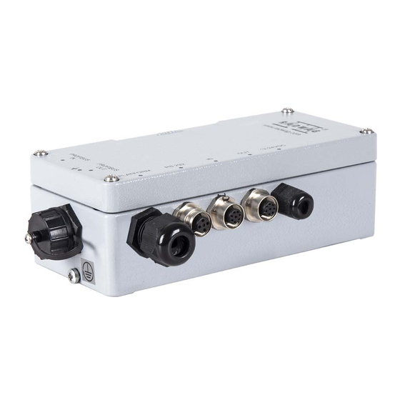
Page 7: General View
MW-01 mass converter, dimensions 6.3. Connectors MW-01 mass converter ver1 features RS232, RS485, Ethernet cables, they are fed through cable glands. MW-01 mass converter ver2 features 2 connectors, PROFIBUS IN and PROFIBUS OUT, and RS232 cable fed through the cable... -
Page 8: Rs232 Connector
6.3.1. RS232 Connector Signals are transmitted via cable fed through a cable gland M16. The cable is connected to joint J5 of the main board of MW-01 mass converter. 6.3.2. RS485 Connector Signals are transmitted via cable fed through a cable gland M16. The cable is connected to joint J5 of the main board of MW-01 mass converter. -
Page 9: Diagrams Of Connection Cables
Pin arrangement Pin1 – NC Pin2 – A PROFIBUS IN Pin3 – NC (male) Pin4 – B Pin5 – NC Pin1 - +5V Pin2 – A PROFIBUS OUT Pin3 – GND (female) Pin4 – B Pin5 – NC 6.4. Diagrams of Connection Cables 'Mass converter’... -
Page 10: Technical Specifications
'Mass converter' – 'Ethernet' cable (PT0014) 'Mass converter' – 'IN/OUT' cable (PT0146) 6.5. Technical Specifications MODEL MW-01 ver.1 MW-01 ver.2 RS232, RS485, Communication interface RS232, PROFIBUS Ethernet 8 ÷ 30 VDC Power supply Housing metal Ingress protection IP 66 -10 °C ÷ 40 °C... -
Page 11: In/Out Parameters
Verification units 10 000 Maximum input signal gain 19.5 mV 0.5 µV Minimum voltage per verification unit 80 Ω Minimum load cell impedance 1200 Ω Maximum load cell impedance Load cell excitation voltage 5 VDC Load cell type 4 or 6 wires + shield Platform quantity 2IN/3OUT Standard... -
Page 12: Start-Up
‘MwManager’ software is to be found in the ‘MwManager’ user manual. 8. INSTALLER INSTRUCTION The MW-01 mass converter can be a base component of a load cell scale. 8.1. 6-Wire Load Cell Connection Connect 6-wire load cell to the main board following the diagram below:... -
Page 13: 4-Wire Load Cell Connection
Connection Load cell signal REMARKS SHIELD Refer to section 8.3 REF+ SENSE + JP1 not to be soldered REF- SENSE - JP2 not to be soldered OUTPUT+ OUTPUT- +EXC INPUT+ -EXC INPUT- 8.2. 4-Wire Load Cell Connection Connect 4-wire load cell to the main board following the diagram below: 4-wire load cell connection Connection Load cell signal... -
Page 14: Connecting Load Cell's Cable Shield
E – solder pad on A/D converter board. 9. FACTORY PARAMETERS In order to be able to edit and save factory parameters to the MW-01 mass converter's memory, it is necessary to put a jumper allowing access to the factory parameters. -
Page 15: Factory Parameters
Wait for connection to be established between the mass converter and the 'MwManager’ software, go to <Parameters / Factory parameters> submenu. Factory parameters are set into groups: Adjustment, Weighing, Information, Converter. To access a given group, select a respective tab. Factory parameter window 9.2. -
Page 16: Parameter Value Modification
Declaring whether the scale is verified or not. Verified YES - NO YES - verified scale, NO - non-verified scale. Start mass determination (refer to section Determine start mass 9.4.1). Determine adjustment Adjustment factor determination (read section factor 9.4.2). Restoring default adjustment parameter... -
Page 17: Adjustment Factor Determination
It enables correct calibration of the weighing device away from the place of use. The gravitational correction value must be entered with reference to tables prepared by „Radwag Balances and Scales” or calculated using the below formula: Gcor ... -
Page 18: Linearity Correction
9.6. Linearity Correction „Linearity” tab enables access to thresholds and linearity deviations. Linearity correction window Where: Press to zero all threshold values. To zero the deviations and the thresholds, select <Zero thresholds while zeroing linearity> option. Press to zero a value of a particular threshold / deviation. Press to determine deviation of a particular threshold. -
Page 19: Error Messages
10. ERROR MESSAGES Err2 Value out of zero range. Err3 Value out of tare range. Err8 Taring/zeroing time out of range. NULL Zero value from converter. FULL Weighing range exceeded. Display capacity out of range. Start mass error, indication out of range (-5% – +15% of start mass).
Need help?
Do you have a question about the MW-01 and is the answer not in the manual?
Questions and answers