
Related Manuals for CertainTeed BOLT 3


Summary of Contents for CertainTeed BOLT 3
- Page 1 BOLT 3 OPERATION MANUAL PARTS - SERVICE - ACCESSORIES 863.294.3206 / 800.237.7841 www.certainteedmachineworks.com PLEASE READ THIS MANUAL BEFORE PLACING YOUR NEW BOLT 3 INSULATION BLOWING MACHINE INTO SERVICE...
-
Page 2: Table Of Contents
Contents Introduction ........................1 Specifications ........................1 Accessory Kit ........................1 Optional Equipment ......................2 Safety ..........................3 Main Components ......................5 Machine Operation ......................8 Preventive ........................9 Electrical Schematic ………………………………………………………………………… 15 Troubleshooting ......................13 Warranty ........................16 Figure Index Figure Page Description... -
Page 3: Introduction
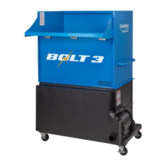
Introduction CertainTeed Machine Works BOLT 3 Insulation Blowing Machine is designed for use by professional contractors, new insulation contractors, renovators and remodelers. The BOLT 3 machine has a two-piece design, a 25 ft capacity hopper, dual-blowers for a better blowing arc, and a removable electrical panel for ease of maintenance. The BOLT 3 high-performance blowing machine is an industry leading insulating machine offering superior material conditioning, long-lasting dependability, and ease of use. -
Page 4: Optional Equipment
Optional Equipment Wireless Remote (SKU # 163606) 150’ Wired Remote Cord (SKU # 212344) 100’ Hose Package (SKU #212217) SKU # Quantity Description 162885 Mark II Clear Hose 3.0" X 50' 210991 Hose Sleeve, 3.0" 162483 3.0" SS Hose Clamp ... -
Page 5: Safety
Safety The BOLT 3 insulation blowing machine has full mechanical guarding and electrical disconnects for your safety. When using the BOLT 3 machine the following precautions should always be followed: Read all the instructions before using the insulation blowing machine. - Page 6 Never reach into the machine while it is operating. Before you start the BOLT 3 insulation blowing machine, make sure the machine hopper is securely attached to the base, the hopper is free of foreign objects, all guards are in place, the slide gate is not completely closed and the hose is attached firmly to the outlet port.
-
Page 7: Main Components
Main Components Before using the BOLT 3 insulation blowing machine this machine, familiarize yourself with the main components, operating features and safety requirements. Do not let familiarity with this machine make you careless. Base: Bottom of the machine that is a reinforced steel base that houses the electric motor, speed reducer, caster wheels, airlock feeder, and blowers. - Page 8 Figure 1...
- Page 9 Control Panel Components: 1. Emergency Stop: Depress to stop the machine; turn and pull to release 2. Ready Light: The white light indicates the machine has satisfied all safety constraints and is ready for use 3. Air Speed Control: Used air flow adjustment 4.
-
Page 10: Machine Operation
Machine Operation Engage locks on casters. Install Hopper onto machine base. Set slide gate to proper position; Position #4 for most open blow fiberglass applications; Position #5 for cellulose Install 3.0” diameter blow hose onto Airlock Feeder outlet port; 100’ recommended Plug machine in using two approved/supplied power cords. -
Page 11: Preventive
Airlock Feeder: Worn or torn seals can greatly affect the BOLT 3 performance allowing insulation and air to escape the feeder, producing a slow feed rate and lower coverage. - Page 12 Seal Replacement 3 & 4 Figure 3 1. Remove the front guard to gain access to the Feeder 2. Remove the drive chain from the sprockets. 3. Remove the set screws securing the 16T sprocket to the airlock feeder shaft. 4.
- Page 13 Figure 4 Figure 5 7. If you have trouble pulling the rotor assembly out of the housing remove the rear cover “6A” and lightly pushing on the back of the shaft “6B” to loosen the shaft from the housing. 8. Pull the rotor assembly out towards the front of the housing to remove. It may be necessary to pull and rotate the assembly counter-clockwise to free it from the housing.
- Page 14 11. Re-assemble with new seals in the reverse order of disassembly. Be sure to place the cutout in rubber seal towards the shaft! 12. To install the Rotor Assembly back into the housing be sure to push and rotate counter- clockwise to insure that the rubber seals are seated into the housing.
-
Page 15: Troubleshooting
Troubleshooting Before preforming any work outlined in this section please read through it thoroughly. CTMW recommends that only Certified Mechanics and Certified Electricians preform the steps outlined below. Failure to do so can result in serious bodily injury or even death. If after exhausting the steps outlined below your machine is still not functioning properly please call our technical department at 1-800-237-7841 for further assistance. - Page 16 No material flow: No material in hopper Unplug power supply. Check for material bridging in the hopper or if any jams have occurred Object restricting flow in the machine or too much material in hopper has stopped the machine Chains are loose or disconnected 5.
-
Page 17: Electrical Schematic
Figure 8... -
Page 18: Warranty
Preventive Maintenance Record Date Job Description Performed By _____________________________________________________________________________________ _____________________________________________________________________________________ _____________________________________________________________________________________ _____________________________________________________________________________________ _____________________________________________________________________________________ _____________________________________________________________________________________ _____________________________________________________________________________________ _____________________________________________________________________________________ _____________________________________________________________________________________ _____________________________________________________________________________________ _____________________________________________________________________________________ _____________________________________________________________________________________ _____________________________________________________________________________________ _____________________________________________________________________________________ _____________________________________________________________________________________ _____________________________________________________________________________________ _____________________________________________________________________________________ _____________________________________________________________________________________ _____________________________________________________________________________________ _____________________________________________________________________________________ _____________________________________________________________________________________ _____________________________________________________________________________________ Warranty... - Page 19 LIMITED TWO-YEAR WARRANTY CertainTeed Machine Works (the Company) warrants to each original purchaser (the Buyer) of its blowing equipment that such products will be free of manufacturing defects for a period of two years from the date of shipment to the Buyer, except that no warranty is made with respect to: 1.
- Page 20 BOLT 3 Operation Manual – Sept 2020...
Need help?
Do you have a question about the BOLT 3 and is the answer not in the manual?
Questions and answers