Advertisement
Quick Links
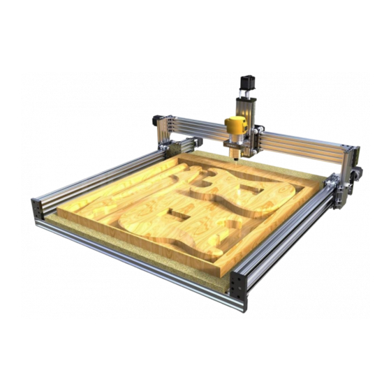
CNC Machines Laser Upgrade Instructions
This part of the documentation is connected with popular CNC machines Laser Upgrades.
Basically, with the help of the PLH3D-CNC Adapter, it is possible to connect the laser head to almost
any CNC machine and turn it into laser engraver. A very important thing besides the connection is G-
Code generating. It differs from the standard G-Code. The laser needs to be switched off during the
idle movement while spindle can be left rotating. The most similar thing in Laser and Spindle G-code
is the power and the rotation speed. PWM signal is controlling the rotation speed of the spindle
while the same signal can be used to control the laser power. Usually, it is done with S0 - S255
command but different CNC Software and Controllers are using different values, for example, S0 -
S1000.
Copyri ght © 2020 by Tomorrow's Sys tem Sp. z o.o. Al l Ri ghts Res erved.
Advertisement

Subscribe to Our Youtube Channel
Related Manuals for Opt Lasers Grav PLH3D-6W Series


Summary of Contents for Opt Lasers Grav PLH3D-6W Series
- Page 1 CNC Machines Laser Upgrade Instructions This part of the documentation is connected with popular CNC machines Laser Upgrades. Basically, with the help of the PLH3D-CNC Adapter, it is possible to connect the laser head to almost any CNC machine and turn it into laser engraver. A very important thing besides the connection is G- Code generating.
- Page 2 Support a nd Ma nua l s LEAD/WorkBee CNC Laser Upgrade Setup Guide for PLH3D-6W-Series Laser Heads Contact and Shipping: Company Information: Tomorrow's System Sp. z o.o. Tomorrow's System Sp. z o.o. Okulickiego 7/9 hala G39 Pułaskiego 125/35 05-500 Piaseczno 15-337 Białystok Poland Poland...
- Page 3 Extending the machine by adding a quality laser head to it, such as Opt Lasers PLH3D-6W-Series laser head, enables unmatched fast precision engraving and cutti ng of various types of materials.
-
Page 4: Included Parts
Support a nd Ma nua l s Included Parts 4 / 26... - Page 5 Support a nd Ma nua l s Laser Safety Only person with specialized training and appropriate laser safety knowledge can use and maintain the laser head. The laser head operator must be aware of laser radiation hazard. While laser head is operating protection Laser Glasses designed for 190 – 540 nm (OD 7+) should be used.
- Page 6 Support a nd Ma nua l s Mounting Setup To mount the PLH3D-6W-Series laser head, the following tools are required: Small flat-head screwdriver; § H2.5 hex key; § H3 hex key; § H4 hex key; § 8 mm spanner; § A few zip ties (optional).
- Page 7 Support a nd Ma nua l s 4. Install the LEAD mount (with a relevant element of the docking station) onto the spindle holder. The LEAD mount is designed to be installed on the left, right, or front side of the spindle holder. ·...
- Page 8 Support a nd Ma nua l s · Use an M5x18mm spacer to be able to install the laser mount without removing the dust shoe (possible only for mounting on the left- and right-hand sides). Mounting the docking station on the left-hand side is the recommended option, because, in this scenario, the laser cable will not face the user.
-
Page 9: Wiring Setup
Support a nd Ma nua l s Wiring Setup 1.Connect one end of the PLH3D-CNC Adapter-to-Laser-Head Cable to the docking station on the LEAD PLH3D Mount. Secure this cable to the mount with a zip tie. 2. Further zip ties can be utilized to fasten the cable at the top of the Z-axis and then along the other side of the X-axis, as shown below: 9 / 26... - Page 10 Support a nd Ma nua l s 3. Next, secure the cable along the X-axis drag chain using zip ties or by putti ng it through it. 4. For the next step, pass the cable around the X-axis motor and then secure the cable along the Y- axis drag chain in a similar fashion as in the previous step.
- Page 11 Support a nd Ma nua l s 5. Next, connect the laser head cable to the output of the PLH3D-CNC Adapter. 6. Then, connect the LEAD Signal Cable to the output (TOOL HEAD) of the BlackBox controller. 11 / 26...
- Page 12 Support a nd Ma nua l s The appropriate connection diagram between the PLH3D-CNC Adapter and the BlackBox Controller is as follows: 7. Please follow it by connecting the BlackBox signal cable to the input of the PLH3D-CNC Adapter. 8. Finally, plug the 19 V, 2.5 A desktop power supply into the socket on the PLH3D-CNC Adapter. 12 / 26...
- Page 13 PLH3D-CNC Adapter Settings The PLH3D-CNC Adapter should have the “0” program set. A detailed description can be found in the CNC Adapter Manual on the Opt Lasersʼ oe site. How to Check Enable Option in PLH3D-CNC Adapter Note: After turning the key switch On, the current Enable Option setti ng will be displayed with indication LEDs for a second.
- Page 14 Support a nd Ma nua l s LEDs will show a combination corresponding to the current setti ng. Do not press Mode button again. To quit without saving, wait for five seconds until Power LED is lit or turn the switch key off. How to Set Enable Option in PLH3D-CNC Adapter Turn the key switch OFF.
- Page 15 Support a nd Ma nua l s LEDs will show a combination corresponding to the current setti ng. To step to the next setti ng, press the mode button once. Keep pressing the mode button till you find the setti ngs that you wish to be set. To save the current setti ng, wait five seconds with the button released.
-
Page 16: Software Setup
Support a nd Ma nua l s Software Setup To cut or engrave, it is necessary to generate the appropriate G-code using the following commands: Laser ON Laser OFF SXXX PWM duty, where XXX is a number between 0 and 1000 (e.g.: 0 = 0% and 255 = 100%. - Page 17 Support a nd Ma nua l s Setting Working Distance Some engraving applications may require small focus spot, i.e. high-resolution engraving, detailed engraving. PLH3D-6W Series laser head has adjustable focal length and exchangeable lens. This future allows it to fulfill broad range of engraving applications. Shorter focal length of the laser head produces a smaller beam spot (higher power density).
- Page 18 Support a nd Ma nua l s To obtain the highest power density, which results in the better engraving performance, we recommend making fine adjustments to the distance of the laser head and the engraving material. This adjustment should be done after performing coarse adjustment. The process is similar to the coarse adjustment process expect steps in Z-axis, they are smaller to make adjustment precise.
- Page 19 Support a nd Ma nua l s First Job 1. Once the PLH3D laser head has been properly connected, place a piece of plywood on the table within the working range of your LEAD CNC machine. Move the laser head in the X- and Y- axis to have the laser module stationed just above the bottom left corner of the plywood fragment.
- Page 20 Support a nd Ma nua l s 4. Click the “setzero XYZ” button. Doing so will set the XYZ coordinates to zero at this chosen position. 5. Open the OpenBuilds G-CODE generator. 20 / 26...
- Page 21 Support a nd Ma nua l s 6. A window will pop up, prompting for a machine configuration. Please select the correct controller and the appropriate machine model as shown in the picture below: 7. In the fourth section of the machine configuration, namely “Tool initialization”, select "Turn Laser on and Off: Dynamic Power (M4 / M5)".
- Page 22 Support a nd Ma nua l s 8. In the subsequent section of the machine configuration, you can set customized parameters for the machine working area and laser power. Furthermore, it also shows the G-code commands and setti ngs. 9. Once all desired setti ngs for the machine configuration have been set, click on the “Save“ button. 22 / 26...
- Page 23 Support a nd Ma nua l s 10. You can create a text or an image or a DXF file. 11. Select the text and then click on the "+ Add" button in the Toolpaths section. Next, click on the "Create a new operation"...
- Page 24 Support a nd Ma nua l s 13. After saving the setti ngs generate the relevant G-Code by clicking on the “Generate G-Code” button and save it. 14. Save the generated G-Code by clicking on the save button, labeled with “1”. Having written the file name of choice, click on the save button, labeled with “2”, as depicted in the picture below.
- Page 25 Support a nd Ma nua l s 15. Open the “OpenBuild Control”. Then, upload the generated G-Code. 25 / 26...
- Page 26 Support a nd Ma nua l s 16. Put the Laser Safety Glasses on! 17. Use the key and the ARM/DISARM button to turn on the PLH3D-CNC Adapter and to arm the laser head. POWER and ARMED LEDs should light up. 18.
Need help?
Do you have a question about the Grav PLH3D-6W Series and is the answer not in the manual?
Questions and answers