Advertisement
Quick Links
Product User Manuals
Contact and Shipping:
Tomorrow's System Sp. z o.o.
Okulickiego 7/9 hala G39
05-500 Piaseczno
Poland
tel.: +48 515 180 752
e-mail:
contact@optlasers.com
Copyri ght © 2020 by Tomorrow's Sys tem Sp. z o.o. Al l Ri ghts Res erved.
Company Information:
Tomorrow's System Sp. z o.o.
Pułaskiego 125/35
15-337 Białystok
Poland
NIP: PL5423238556
REGON: 200866868
Advertisement

Subscribe to Our Youtube Channel
Related Manuals for Opt Lasers GRAV PLH3D-CNC


Summary of Contents for Opt Lasers GRAV PLH3D-CNC
- Page 1 Product User Manuals Contact and Shipping: Company Information: Tomorrow's System Sp. z o.o. Tomorrow's System Sp. z o.o. Okulickiego 7/9 hala G39 Pułaskiego 125/35 05-500 Piaseczno 15-337 Białystok Poland Poland tel.: +48 515 180 752 NIP: PL5423238556 e-mail: REGON: 200866868 contact@optlasers.com Copyri ght ©...
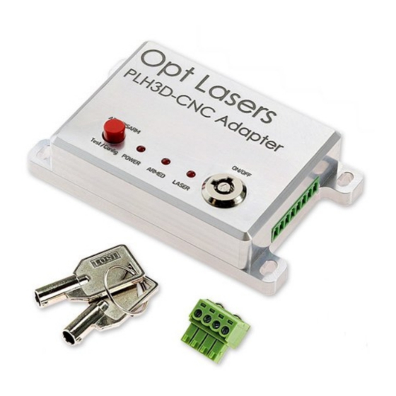
- Page 2 Support a nd Ma nua l s PLH3D-CNC Adapter (center), PLH3D-6W-XF (bottom left), optional cables with CNC machine connector (bottom right), external keylock (top right) and stop button (top left). The PLH3D-CNC Adapter serves as a versatile interface and safety unit connected between a CNC machine and a high-performance PLH3D laser head.
- Page 3 Support a nd Ma nua l s The laser head can be made operational by selecting to “arm” and “disarm” the laser head. Arming means turning the head power supply on; the armed head is then able to generate a laser beam. Disarming (turning the head power supply off) brings the laser head to a safe state where generating a laser beam is altogether impossible.
- Page 4 Support a nd Ma nua l s Controls and Indicators of PLH3D-CNC Adapter Main States of the PLH3D-CNC Adapter: Power Supply - Off; Laser Head - Off; Power Supply - On; Laser Head - Off; Laser Head - Armed; Controlling Signal - Absent; Lasing - No; Laser Head - Armed;...
- Page 5 Support a nd Ma nua l s The detailed description of the distinct sections of the Adapter: LASER HEAD CONNECTOR Attach the laser head cable here. 1.1. EXTERNAL SWITCH CONNECTOR Up to two external switches (e.g., a limit switch, a key switch, or an e-stop) that 2.1.
- Page 6 Support a nd Ma nua l s Dimensions: 6 / 27...
- Page 7 Support a nd Ma nua l s Pinout: Pinout of the cable located between the laser head and the PLH3D-CNC Adapter: Note: If you are using a laser docking station, this cable should be plugged into the laser docking station instead into the laser head. 7 / 27...
-
Page 8: Getting Started
To find out more about how to connect the cables, feel free to have a look at our video guide available at https://youtu.be/MQ5v1CD_rlc d) Remember to subscribe to our YouTube channel. You will immensely benefit from Opt Lasers' hands-on tutorials and inspirations. - Page 9 Support a nd Ma nua l s Press the Mode button once. The Armed and Power LEDs ought to be radiant at this point. If this is not the case, go to the "Troubleshooting" section of the user's manual. Now the laser head will be tested. Press the MOD button continuously for approximately 2 seconds.
- Page 10 Support a nd Ma nua l s Connection to CNC machines 1. X-Carve 10 / 27...
- Page 11 Support a nd Ma nua l s 2. Stepcraft 11 / 27...
- Page 12 Support a nd Ma nua l s 3. Shapeoko Arduino Uno: gShield (grblShield v5): 12 / 27...
- Page 13 Support a nd Ma nua l s 4. ZMorph Opt Lasers Signal Cable for the PLH3D-6W-ZMorph Laser Head: ZMorph itself (pins at adapter same as above): 13 / 27...
- Page 14 Support a nd Ma nua l s 5. WorkBee Duet Controller 14 / 27...
- Page 15 Support a nd Ma nua l s CNC xPro v3 Controller CNC xPro v4 Controller 6. CNC Routers Parts / Avid CNC 15 / 27...
- Page 16 Support a nd Ma nua l s Smooth Stepper 7. BlackBox Motion Control System 8. CSMIO Controller 16 / 27...
- Page 17 Support a nd Ma nua l s 9. Pokey57 CNC Controller 10. EleksMaker 11. Openbuilds 17 / 27...
- Page 18 Support a nd Ma nua l s PLH3D-CNC Adapter Enable Options Specific CNC machines issue special “disable/enable” signals for turning the laser beam off and on. The PLH3D-CNC Adapter can be set in such a way that the laser beam is enabled only for certain states on two Enable inputs and disabled in other cases.
- Page 19 Support a nd Ma nua l s 5. TOGGLING means: - LOW-to-HIGH or HIGH-to-LOW transitions, 200 ms or less apart. How to Check Enable Option in PLH3D-CNC Adapter Note: After turning the key switch On, the current Enable Option setti ng will be displayed with indication LEDs for a second.
- Page 20 Support a nd Ma nua l s LEDs will show a combination corresponding to the current setti ng. Do not press Mode button again. To quit without saving, wait for five seconds until Power LED is lit or turn the switch key off. How to Set Enable Option in PLH3D-CNC Adapter Turn the key switch OFF.
- Page 21 Support a nd Ma nua l s LEDs will show a combination corresponding to the current setti ng. To step to the next setti ng, press the mode button once. Keep pressing the mode button till you find the setti ngs that you wish to be set. To save the current setti ng, wait five seconds with the button released.
- Page 22 Support a nd Ma nua l s For Advanced Users Block Diagram 22 / 27...
- Page 23 Support a nd Ma nua l s EXTERNAL SWITCH Connector Pinout with Description Pin no. Name External switch Switch A Switch B The switches are connected in series with the power supply feeding the power to the laser head through the arming relay. Opening any of the switches disconnects the supply of the laser head and thus disarms it.
- Page 24 Support a nd Ma nua l s CONTROL Connector Pinout with Description Pin no. Name Description ANGIN 5V INPUT A proportional (analogue) modulation input, operating in a 0-5 V range (corresponds to 0% - 100% levels respectively). The input withstands voltages up to 24 V DC. The input impedance is 3.9 kΩ.
-
Page 25: Enable Options
Support a nd Ma nua l s Enable Options Specific CNC machines issue special “disable/enable” signals for turning the laser beam off and on. The PLH3D-CNC Adapter can be set in such a way that the laser beam is enabled only for certain states on two Enable inputs and disabled in other cases. -
Page 26: Additional Features
Support a nd Ma nua l s Additional Features Applicable to PLH3D-CNC adapters sold after 20-July-2020: Enable Option Check at Power-on. After turning the key switch ON, the current Enable Option setti ng will be displayed with indication LEDs for a second. Please refer to the table with Enable Option LED combinations, which can be found in the preceding subsection, namely Enable Options. -
Page 27: Troubleshooting
Support a nd Ma nua l s Troubleshooting Before proceeding with the troubleshooting, please make sure you followed all the steps described in the "Getti ng Started" section. If you find any problems using the PLH3D-CNC Adapter, the following table should be able to address it.
Need help?
Do you have a question about the GRAV PLH3D-CNC and is the answer not in the manual?
Questions and answers