Table of Contents
Advertisement
Quick Links
Advertisement
Table of Contents

Related Manuals for Dynamic DX-REMG91


Summary of Contents for Dynamic DX-REMG91
- Page 3 All other brand and product names, fonts, and company names and logos are trademarks or registered trademarks of their respective companies. Dynamic owns and will retain all trademark rights and Dynamic or its licensors own and will retain all copyright, trade secret and other proprietary rights, in and to the documentation.
-
Page 4: Table Of Contents
Contents Introducing DX ............1 Introducing the G91 ..........3 G91 Operation ............5 Display Area ................5 3.1.1 Drive Mode Display ............5 3.1.2 Actuator Mode Display ..........6 3.1.3 ECU Modes ............... 7 3.1.4 Lighting Mode ..............7 3.1.5 Status Information ............ - Page 5 Installation and Testing ......... 40 Mounting ................... 40 Mounting Accessories ............. 41 G91 Connection with the DX System ........42 Testing ..................43 Programming G91 ..........46 Introduction ................46 Auto Download ................ 47 Programming with Wizard ............48 6.3.1 Wizard Section: REMG91(S) Specific Options ... 48 6.3.2 Wizard Various Sections: Chair Speed Options ..
- Page 6 : Issue 3 – February 2012 GBK64048...
-
Page 7: Introducing Dx
1 Introducing DX DX is a modular, expandable power wheelchair control system. This modularity allows the system to be expanded and customized to particular end-user needs and handles the requirements from driving to full environmental control. A power module and secondary remote are required along with two DXBUS cables to form the base of a G91 DX system. - Page 8 THIS PAGE IS LEFT BLANK INTENTIONALLY – February 2012 GBK63648 Issue 3...
-
Page 9: Introducing The G91
DX-REMG91 Featuring three jack sockets for external switches DX-REMG91S Building on the functionality of the DX-REMG91 by adding single switch scanning. A DX wheelchair control system comprises of two or more compatible modules. Each module has its own installation manual. - Page 10 THIS PAGE IS LEFT BLANK INTENTIONALLY – February 2012 GBK63648 Issue 3...
-
Page 11: G91 Operation
3 G91 Operation 3.1 Display Area The G91 display area is a sophisticated means of providing information and feedback about the system and functionality. The display consists of functional groups of icons and indicators, all shown illuminated below. 3.1.1 Drive Mode Display Drive Mode Display Item Description... -
Page 12: Actuator Mode Display
3.1.2 Actuator Mode Display Actuator Mode Display Item Description Actuator Mode Displays that actuator mode is selected. Used in all Indicator modes Actuator Icons The selected actuator is indicated by a flashing icon. Only enabled actuators are illuminated. Left Foot Rest DX-CLAMB output 3 Seat Tilt-In-Space DX-CLAMB output 1... -
Page 13: Ecu Modes
3.1.3 ECU Modes ECU Mode Item Description ECU Mode Indicator Displays that ECU mode is selected . ECU2 Indicators Displays that ECU2 mode is selected. 3.1.4 Lighting Mode Lighting Mode Item Description Headlight Indicator Shows the status of the headlights. When illuminated, the headlights are on. -
Page 14: Status Information
3.1.5 Status Information Status Information Display Item Description System Status LED Green LED denotes the status of the system: on steady indicates no system faults, flashing indicates a fault. Refer Section 7.3 - Flash Codes Battery Gauge 6 multi-coloured LEDs indicate charge state of the battery. -
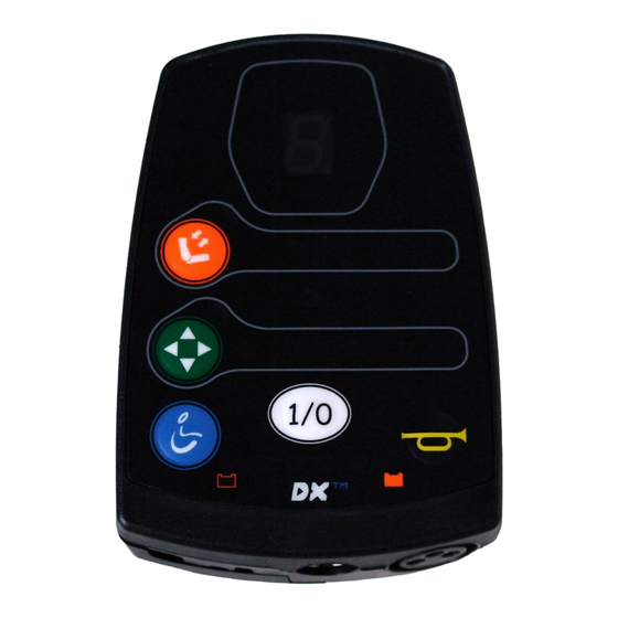
Page 15: Keypad
3.2 Keypad The G91 has the following keypad layout: DX-REMG91 1. On/Off Button Press the On/Off button to turn the power on. The current battery charge will be indicated and the System Status LED will illuminate. Press the On/Off button again to turn the power off. - Page 16 3. Drive Mode Each press of the Mode button will increment the drive profile, up to the maximum configured value and then back to profile 1. The current drive profile will be shown in the 7 Segment Display. If Accessory or ECU functions are being operated, a press of the Mode button will return to the last used drive profile.
- Page 17 4. ESK (Environmental Shortcut Key) Pressing the ESK will navigate you to the last used ECU mode, e.g. ECU1 mode. If you are already in ECU Mode, a press of ESK will take you to the next available ECU mode, e.g. ECU2. To return to Driving, simply press the Drive Mode button.
-
Page 18: Jack Sockets
3.3 Jack Sockets Jack Socket Position and labelling Jack sockets are provided on the G91 for accessing functions via 3rd party switches. These connections are protected by a screw down cover and are clearly labelled inside the cover. Maximum tightening torque for the M3 cover screw is 0.6 Nm. –... - Page 19 When the 3 party switches are connected, ensure the wiring is routed suitably and exits from the cable outlet in the cover as shown below. Chapter 3 : G91 Operation...
- Page 20 1. On/Off Jack Socket The function of the switch connected to this jack socket is identical to the On/Off button. Press the On/Off switch to turn power on. Press the On/Off button again to turn the power off. 2. Mode Jack Socket The function of the Mode jack socket is different to the keypad‟s Drive Mode Button.
- Page 21 3. AUX Jack Socket The AUX jack socket has a different feature in each mode to maximise the usability. Drive Mode. Sounds the horn for as long as the button is pressed. ECU1 Mode. Operates ECU1 channel 5, to give a 5 ECU function, typically for a „Mouse mover‟...
-
Page 22: Jack Socket Switch Monitoring
3.4 Jack Socket Switch Monitoring The installer needs to carefully consider the implications of failure of either the „Mode„ or „Aux‟ switches plugged into the G91 jack sockets or equivalent functions within the system installation such as DX-ARC-SWB. This is especially true of „Aux‟ switch with the G91S when set up as a single switch scanning device. -
Page 23: Actuator Options
3.5 Actuator Options The G91 has a number of actuator options to maximize flexibility and simplicity of operation. The programmed Joystick Switch Threshold will determine the joystick deflection required to operate any Actuator functions. The programmable option Both Leg Rests Enable allows extra flexibility by simultaneous operation of DX- CLAMB channels 3 and 4, refer Section 5.3. -
Page 24: Latched Actuators
3.5.2 Latched Actuators The programmable option Latched Actuators allows actuator channels/seat movements to be latched. A user input will cause the actuator to start moving and will continue to move. When an actuator is moving, any user input will stop the actuator. Options are: None/All/Seat Raise Only/Tilt In Space Only. -
Page 25: Latched & Bi Directional Actuators
3.5.4 Latched & Bi directional actuators Latched Actuators can be combined with Bi directional Actuators to give a sophisticated solution. When an actuator is moving, any user input will stop the actuator. Note: When using Latched Actuators, if the actuator is required to travel along its full length without interruption the parameter Actuator Timeout should be set to a value(seconds) slightly higher than the maximum travel time of the actuators. -
Page 26: Quadrant Rim Mode Actuators
3.5.5 3 Quadrant RIM Mode Actuators In 3 Quadrant RIM Modes all actuator functions are controlled with only two user inputs, left and right. This gives extra flexibility for head control applications. In 3 Quadrant RIM Modes, actuator control is always bi directional and the parameter Bi directional Actuators is ignored. -
Page 27: Ecu Modes
3.6 ECU Modes ECU Modes enable the G91 to be used with DX-ECU Modules to interface to 3 party devices, such as environmental controls and communication aids. The G91 can support two ECU modes using two separate DX-ECU modules. Each DX-ECU is configured as either ECU1 or ECU2 using the „Molex jumper‟ connector provided. -
Page 28: Ecu 2 Mode
3.6.2 ECU 2 Mode ECU2 uses dedicated icons to assist pattern recognition and user familiarisation. When ECU2 mode is first selected the ECU indicator and the diamond shaped icon will illuminate. The ECU outputs to be operated are selected by scrolling through the four symbols using the left and right direction of the joystick (or input device) Once the relevant outputs have been selected the... -
Page 29: Lighting Mode
3.7 Lighting Mode When in Lighting Menu Mode, the 7 Segment display shows 3 horizontal lines. Moving the joystick forward will toggle the Headlights. Moving the joystick left will toggle the Left turn Indicators. Moving the joystick right will toggle the right turn Indicators. -
Page 30: Quadrant Rim Modes
3.8 3 Quadrant RIM Modes To provide maximum versatility and flexibility, there are two modes of operating G91 with a 3 Quadrant RIM input device, such as a head-control. Refer to Programming Section 6.3.1 – „Input‟. This enable the desired drive input to be selected. -
Page 31: Quadrant Rim Switch Mode
3.8.2 3 Quadrant RIM Switch Mode This is typically used with a switch based head control where the user can operate three direction commands, forward, left and right. A fourth switch is used to change mode and to „toggle‟ forward to reverse direction using long and short presses. -
Page 32: Joystick Only Operating Mode
3.9 Joystick Only Operating Mode This mode allows all functions to be controlled with a 4 quadrant joystick. Refer to Programming Section 6.3.1 – „Input‟. This enable the desired drive input to be selected. This mode can be operated by any joystick source where the user can operate all four direction commands. -
Page 33: Joystick Only Menu Map
3.9.1 Joystick Only Menu Map Chapter 3 : G91 Operation... -
Page 34: The Joystick
3.10 The Joystick The joystick for the G91 is always provided in the form of a secondary remote such as a DX-RJM. Moving the joystick will cause the powerchair to drive in that direction. The amount of joystick movement will determine the speed that the powerchair will move in that direction. -
Page 35: Charging
Pin 2 Battery Negative (B-) Pin 3 Inhibit The inhibit signal must be provided from pin 2 to pin 3 of the battery charger plug. Dynamic Controls recommends the use of suitable Neutral plugs only. Warning: The charger plug must be removed by applying force in the direction of the pins. -
Page 36: G91S Operation
4 G91S Operation As described within the operation of the G91 unless otherwise stated. 4.1 Scanning Aimed at users who can only reliably press one button “Aux”. The use of 2 button scanning is supported. The use of a mode button enables the user to return to the home level without waiting for the complete scan cycle. -
Page 37: Mode Selection (Home Level)
4.2 Mode Selection (Home Level) With the G91S powered press the AUX button to start the G91S scanning through the modes of operation that are available. The G91S will scan through at the programmed scan rate for the number of cycles set before returning to standby mode if no operation is selected. -
Page 38: Driving
4.3 Driving During mode selection pressing the AUX button when the 7-Segment display is illuminated will enter drive mode. The Display will then scan through the drive profiles available, 1, 2, n … Press AUX when desired drive profile is lit to select the profile. The scan pattern will start. -
Page 39: Scan Pattern Selection
4.3.1 Scan Pattern Selection The G91S offers a range of scan patterns which can be selected using the Wizard software. The LED‟s 1-6 shown on the right are scanned according to the patterns listed below. The desired pattern is selected using the „Scan Pattern‟ parameter in Wizard Available Scan Pattern sequences are: Pattern 1:... - Page 40 Pattern 3: 1 – 2 – 1 – 3 – 1 – 4….. Pattern 4: 1 – 5 – 1 – 6 – 1 – 2 – 1 – 3 – 1 – 4 ….. – February 2012 GBK63648 Issue 3...
-
Page 41: Actuator Scanning Mode
4.4 Actuator Scanning Mode Press the Aux button when the actuator LED is lit to enter actuator mode. The G91S will scan through the available actuators Press Aux button to select an actuator when its symbol is illuminated. The Extend LED (5) will flash, pressing the AUX button will drive the actuator. The operation can be either Momentary or Latched, this is programmable via Wizard. -
Page 42: Ecu Scanning Modes
4.5 ECU Scanning Modes 4.5.1 ECU1 Mode When using the scanner function ECU1 Mode only provides a momentary output on Channel 1 (ECU1-1) (Pin 1) Pressing the AUX button when only the ECU Mode LED is illuminated will „activate‟ the Channel 1 output. Once the switch is released the G91S will continue to scan through the available modes. -
Page 43: Lighting Scanning Mode
4.6 Lighting Scanning Mode To access the Lighting menu the relevant parameters need to be enabled within Wizard (See section 6.3). To activate the Lights press „Aux‟ when the Lights symbol is displayed. The scan sequence for the lights is shown below. Pressing „Aux‟ will enable the relevant lights. -
Page 44: Horn Scanning Mode
4.7 Horn Scanning Mode To access the Horn menu the relevant parameters need to be enabled within Wizard (See section 6.3). To Activate the horn press „Aux‟ when the Horn symbol is displayed. – February 2012 GBK63648 Issue 3... - Page 45 THIS PAGE IS LEFT BLANK INTENTIONALLY Chapter 4 : G91S Operation...
-
Page 46: Installation And Testing
5 Installation and Testing 5.1 Mounting All Dimensions in mm The G91 can be mounted on either side of the wheelchair to accommodate users preference. G91 must be mounted using both M5 fixing screws. The selected screw is to provide at least 4mm, best 6mm thread engagement and must not allow penetration of more than 7mm into the case. -
Page 47: Mounting Accessories
5.2 Mounting Accessories DX-GNK-KIT2 Also available is the GME63626 Warning: For safe installation, select a screw length that protrudes no more than 7 mm into the case. Do not over-tighten. Warning: All G91 variants are not waterproof and must be protected from water ingress as appropriate. -
Page 48: G91 Connection With The Dx System
Note: The DX-REMG91 does not support certain modules such as DX-PCMR or DX-IRIS. In addition, the DX-REMG91S is not recommended for use with the DX-RJM-5SW; DX-RJM-SNP and DX-SLM. Should any clarification be required, please contact Dynamic Controls. -
Page 49: Testing
5.4 Testing Ensure that all DX Modules used in your DX System have been installed as specified in their respective Installation Manuals. The G91 needs to be correctly programmed for the appropriate wheelchair application prior to testing. A suitable DX secondary remote, input device must be connected to the DX system. Examples include the DX-RJM. - Page 50 Perform the remainder of the tests as outlined in the Testing sections of the Installation Manuals of all other DX Modules used on the wheelchair. Repeat testing as required until chair performance is as expected. Note: The first time the G91 is turned on, the System Status LED will flash a fault.
- Page 51 THIS PAGE IS LEFT BLANK INTENTIONALLY Chapter 5: Installation and Testing...
-
Page 52: Programming G91
DX Remote and Power Module being the modules most responsible for defining the driving performance of the DX System. DX can be programmed at 3 points: During manufacturer by Dynamic – Default Programs Prior to shipping, each module is loaded with appropriate default settings. -
Page 53: Auto Download
Existing DX Wizard programs can be converted into G91 compatible programs. Please contact your local Dynamic Representative for details. 6.2 Auto Download The DX System has a feature called Auto Download. It is designed to minimize programming requirements associated with Module servicing by down loading the correct programming to a replacement DX Module. -
Page 54: Programming With Wizard
Parameter Name Description Remote Type Number This not an adjustable Parameter. This is used by Dynamic during the manufacturing process. Input Select the input type for the remote. Normal, 3Q RIM Switched, 3Q RIM Proportional, Scanner, Joystick only. Refer to sections 3 and 4 for details. Normal means the G91 acts like a G90 with a secondary remote. - Page 55 Bi-directional Actuators Set to "Yes" and actuators are operated in both directions with only one input direction; e.g. forward extends actuator, forward again retracts actuator. Can be combined with „Latched Actuators'. Latched Actuators Selects which actuators are latched: None, All, Seat raise only, Tilt in space only.
-
Page 56: Wizard Various Sections: Chair Speed Options
6.3.2 Wizard Various Sections: Chair Speed Options These are the associated parameters that can provide dramatically simplified dealer customisation of the powerchair. Parameter Name Description Chair Speed Enables the parameter Chair Speed and allows the HHP to Enable be used to easily adjust it. Refer to parameter Chair Speed. The OEM enables this parameter if simplified dealer programming is required. -
Page 57: Wizard Section: Remote Control Settings
6.3.3 Wizard Section: Remote Control Settings These parameters provide a new level of user customisation options and are very powerful for special adaptations. Specific applications include 3 party switch control of Mode up, Mode down, Horn and lighting functions. Parameter Name Description ARC always This provides an option for what the actuator 1 and 2... -
Page 58: Optimising Chair Stability & Controllability
6.4 Optimising Chair Stability & Controllability The G91 features an advanced set of parameters to provide improved powerchair stability and are particularly useful for FWD/MWD applications. Wizard Section: Drive Profiles Parameter Name Description Grip Defines the level of assistance G91 will provide in an effort to improve chair stability. - Page 59 Preventing Front Wheel Drive Chairs From Spinning The 3 options for Speed X Turn for Grip, Accel out of a Turn for Grip and Accel into a Turn for Grip are a set of parameters that define a Virtual Restrictor Plate (VRP) specifically designed to improve the safety and controllability of Front and Mid-Wheel Drive chairs.
-
Page 60: Programmable Joystick Throw/Shape
6.5 Programmable Joystick Throw/Shape The G91 features a Programmable Joystick Throw and Shape. These options can be set by the dealer or therapist to reduce the amount of joystick movement required to suit the physical abilities of specific users. Reducing the Pressure or Movement to Operate a Joystick The Short Throw Travel and Short Throw Shape parameters are used together to create custom VRPs on a user by user basis. - Page 61 THIS PAGE IS LEFT BLANK INTENTIONALLY Chapter 6: Programming G91...
-
Page 62: Diagnostics
Plugging a hand held programmer into the G91 when an abnormal condition exists will cause the fault to be displayed. The HHP will display what the detected fault is. DYNAMIC Wizard Wizard is the preferred diagnostics tool in the workshop environment, providing a full fault history and shows any current faults. -
Page 63: Flash Codes
7.3 Flash Codes Flash codes indicate the nature of an abnormal condition directly from the System Status LED. Without the use of any servicing tools, the condition can be simply diagnosed. These flash codes are the same as existing DX products. Flash Code Description Cause / Action... - Page 64 C: The connection from the PM right (M2) connector to its associated motor, or the motor itself, is defective. The connection is either Right (M2) open or short circuit. Motor Fault A: Disconnect the left motor plug & check continuity between the motor pins on M2. A: Ensure there is no continuity between motor &...
- Page 65 C: There is a compatibility problem between DX Modules in the System. The wheelchair will be disabled. A: Consult your Dynamic Service Centre. Module Mismatch C: The data held by the G91 for another DX Module is corrupt or incompatible with that module.
-
Page 66: G91 Specific Indications
7 segment display will show „J‟. To rectify the issue, connect the selected input device and check the program. Please contact your local Dynamic Representative for further details and assistance. 7.5 Limp Mode If the DX System detects some very rare faults, it will revert to Limp Mode. This is a reduced speed mode that recognizes problems, but allows the wheelchair user to limp home where the problem can be assessed. -
Page 67: Battery Gauge
7.6 Battery Gauge The Battery Gauge provides true, useable battery capacity information and also presents battery condition warnings. The number of flashing LEDs on the Battery Gauge shows the type of fault. Flashing LEDS Description Cause / Action C: The battery voltage has exceeded 28V, as measured by the PM. -
Page 68: Specifications
8 Specifications 8.1 Electrical Parameter DX-REMG91(x) Operating voltage range 18V – 32V dc Charger rating 12A RMS Continuous, limited by DXBUS rating Quiescent Current <1mA Off, typically 100mA On 8.2 Mechanical Parameter DX-REMG91(x) Material Plastic Protection Rating IPx4 Shipping Weight... -
Page 69: External Dimensions
8.3 External Dimensions All dimensions in mm Chapter 9: Appendices... -
Page 70: Appendices
9 Appendices 9.1 Programmable Parameters (details) Key: Editable at this level Viewable at this level Not available at this level REMG91 Specific Parameters Values Units Remote Type Number Normal/3Q RIM Switched/3Q Input Proportional/Scanner/Joystick Only ... - Page 71 Note 1. Joystick Source. The G91 does not have a „local‟ or „Master‟ joystick. Available selections are Master/ACU/RJM/Display/ARC/Ext-NV1/Ext- NV2/None. The selections of Display/Ext-NV1/Ext-NV2 are reserved for future expansion and cannot be utilised today. Note 2. HHP Selection of Joystick Source. Selecting an alternative input device on the G91 with the HHP is different to existing DX master remotes, such as DX-REM34 and DX-REMG90.
-
Page 72: Programming Accessories
9.2 Programming Accessories Dynamic DX Programming Accessories Part Description DC Part # Qty/Unit Wizard 5 Kit – Programming Kit Contains DWIZ5-KIT software, cables and adapter (no Dongle) Wizard 5 – Software Only (CD) DWIZ5-SW Wizard Dongle – OEM or Dealer version... -
Page 73: Intended Use And Regulatory Statement
9.3 Intended Use and Regulatory Statement Intended Use The DX-REMG91 family are components of a DX system intended to allow powered wheelchair users interaction with the DX System. The DX-REMG91 offers flexibility in integrating compatible input and output devices, as configured and connected and provides extensive adaptability to meet specific user needs through optimal programmability. -
Page 74: Maintenance
9.5 Warranty All equipment supplied by Dynamic Controls is warranted by the company to be free from faulty materials or workmanship. If any defect is found within the warranty period, the company will repair the equipment, or at its discretion, replace the equipment without charge for materials and labour. -
Page 75: Safety And Misuse Warnings
9.6 Safety and Misuse Warnings Warnings to be included in the User Manual The following warnings are applicable to the installer and must be passed on to the end- user before use of the product. Do not install, maintain or operate this equipment without reading, understanding and following the proper instructions and manuals, otherwise injury or damage can result. - Page 76 While Dynamic Controls has made every effort to ensure that RFI does not cause problems, very strong signals could still cause a problem.
-
Page 77: Electromagnetic Compatibility (Emc)
9.7 Electromagnetic Compatibility (EMC) Dynamic Electronic Controllers have been tested on typical vehicles to confirm compliance with the following appropriate EMC standards: USA: ANSI/RESNA WC/Vol:2 - 1998 Sec 21 Europe: EN12184:1999 Sec 9.8.1-3 National and international directives require confirmation of compliance on particular vehicles. -
Page 78: Environmental Statement
9.8 Environmental Statement This product has been supplied from an environmentally aware manufacturer. Please be environmentally responsible and recycle this product at the end of its life through your local recycling facility. This product may contain substances that could be harmful to the environment if disposed of into a landfill. - Page 79 Chapter 9: Appendices...
-
Page 80: Contact Details
9.9 Contact Details Dynamic has a global network of sales and service centres. Please contact your nearest Dynamic representative for Sales and/or Service advice, or visit our web site: www.dynamiccontrols.com New Zealand – Head Office Australia – Service Agent Dynamic Controls...
Need help?
Do you have a question about the DX-REMG91 and is the answer not in the manual?
Questions and answers