DeWalt DW682 Instruction Manual
Hide thumbs
Also See for DW682:
- User manual ,
- Original instructions manual (109 pages) ,
- Instruction manual (50 pages)
Table of Contents
Advertisement
Quick Links
Advertisement
Table of Contents

Related Manuals for DeWalt DW682


Summary of Contents for DeWalt DW682
- Page 1 WALT Industrial Tool Company, 626 Hanover Pike, P.O. Box 158, Hampstead, MD 21074 Printed in U.S.A. (SEP95-CD-1) Form No. 154527 For information call toll free between 8:00 a.m. and 8:00 p.m. ET, seven days a week. 1-800-4-D WALT (1-800-433-9258). DW682 Copyright 1995...
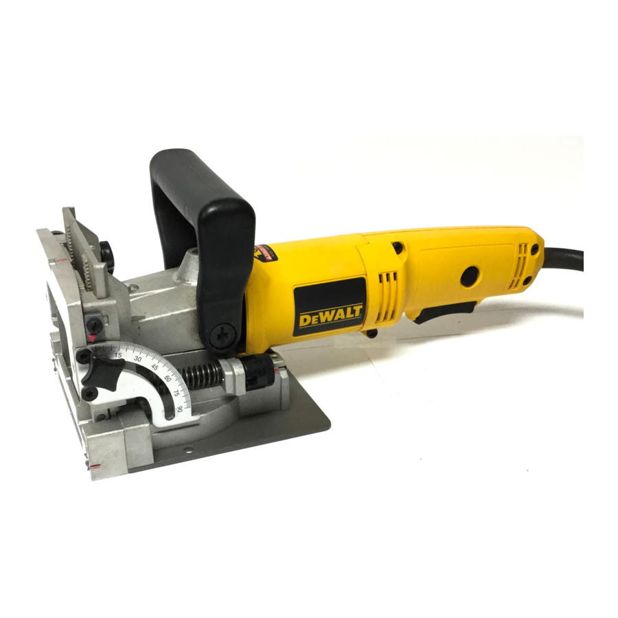
- Page 2 INSTRUCTION MANUAL MANUAL DE INSTRUÇÕES MANUAL DE INSTRUCCIONES DW682 Plate Joiner Fresadora DW 682...
- Page 3 IF YOU HAVE ANY QUESTIONS OR COMMENTS ABOUT THIS OR ANY WALT TOOL, CALL US TOLL FREE AT 1-800-4-D WALT (1-800-433-9258). AUXILIARY HANDLE SPINDLE LOCK Serial Number from Nameplate Date of Purchase LOCK ON BUTTON Save this information for future reference ADJUSTABLE FENCE TRIGGER SWITCH PLUNGE DEPTH...
-
Page 4: Important Safety Instructions
Important Safety Instructions accessories. Inspect tool cords periodically and if damaged have repaired by authorized service facility. Inspect extension cords WARNING: When using Electric Tools, basic safety precautions should periodically and replace if damaged. Keep handles dry, clean, and free always be followed to reduce risk of fire, electric shock, and personal from oil and grease. - Page 5 Introduction FIG 1 AUXILIARY HANDLE Examine Figure 1 and your plate joiner for a few minutes to LOCK KNOB LOCK ON BUTTON become familiar with the various features and the names used to describe them. The following sections will discuss the various HEIGHT ADJUSTMENT controls and you will need to know where they are.
- Page 6 FIG 3 Blade Replacement In time your saw blade will wear out and need replacement. To remove the blade, follow the steps below. EDGE EDGE TO EDGE JOINT 1. Turn off and unplug the plate joiner. MITRE 2. Remove the 4 torx head screws from the bottom of the shoe, JOINT using the T20 torx screwdriver provided.
- Page 7 measured from the workpiece surface to the centerline of the blade FIG 5 ADJUSTMENT (see Figure 6). The adjustable angle feature allows a full range of KNOB settings from 0° to 90 as well as a reverse 45° bevel which allows outside registration on miter joints.
- Page 8 FIG 8 3. FINE DEPTH ADJUSTMENT You may encounter situations where you want to leave a little looseness in your joint so that you can move it slightly before the glue sets up. For these instances a fine depth adjustment has been provided.
- Page 9 6. ADJUSTABLE FENCE SQUARENESS FIG 11 To adjust the squareness of the adjustable fence to the front of the unit, loosen the angle indicating pointer screw, and while holding a square in contact between the adjustable fence and the front of the unit, tighten the lock knob.
-
Page 10: General Operation
FIG 13 remove, pull out firmly. The directional elbow rotates easily to aim the dust in the most convenient direction suitable for the particular application. B. Dust Adaptor (See Figure 12) This attachment, when inserted as described above, allows the use of several common sizes of vacuum hose to be attached for direct vacuum pick-up of the dust. - Page 11 biscuit size to suit most applications. After selecting the biscuit size, FIG 15 set the depth adjustment knob to the corresponding size (see Controls section). Also, be sure the fine depth adjustment is correctly set by first testing in a scrap piece. This is extremely important as you do not want to discover during glue-up that your biscuit slots are not quite deep enough.
- Page 12 FIG 17 joiner’s center registration mark with your layout mark. Turn on the tool and let the blade come up to full speed (approximately 6"-10" 1 second). Grasping the switch handle and auxiliary handle and 2"-3" positioning the fence firmly and squarely against the workpiece, plunge the blade until it bottoms against the stop.
- Page 13 D. Clamp the workpiece and position the tool so that the center FIG 20 indicator mark lines up with the first layout mark (see Figure 18). Turn on the tool and make the plunge cut. Retract the tool and release the trigger to turn the tool off. Repeat for each layout mark. E.
- Page 14 FIG 23 F. Turn on the tool and make the plunge cut. G. Repeat for each layout mark. H. Glue, assemble and clamp the frame. 3. CORNER JOINTS (See Figure 22) Corner joints are another common and excellent application for biscuit joinery.
- Page 15 D. Next, adjust the fence up by an amount equal to the desired FIG 25 offset. Use the scale and pointer located on the right side of the tool under the fence lock knob. E. Clamp the second workpiece, align the tool and make the plunge cut.
- Page 16 FIG 28 B. Layout biscuit locations on the inside of the angle. C. Set up tool by setting fence angle to 45°. Set vertical fence adjustment so that the biscuit is located toward the inside of FENCE ANGLE SETTING OF SIDES JOINT ANGLE OUTSIDE REGISTRATION INSIDE REGISTRATION the joint where material is thicker.
-
Page 17: Double Insulation
LAYOUT If you need assistance in locating any accessory, please contact LINE DeWALT Industrial Tool Company, P.O. Box 158, 626 Hanover Pike, Hampstead, MD 21074 or call 1-800-4-D WALT (1-800-433-9258). Double Insulation... -
Page 18: Motor Brushes
Before using an extension cord, inspect it for loose or exposed wires, damaged insulation, and defective fittings. Make any needed repairs or DeWalt uses an advanced brush system which automatically stops replace the cord if necessary. the drill when the brushes wear out. This prevents serious damage to the motor.
Need help?
Do you have a question about the DW682 and is the answer not in the manual?
Questions and answers