
Subscribe to Our Youtube Channel
Related Manuals for Parker V Series


Summary of Contents for Parker V Series
- Page 1 Model VF Model VP Model VB Versatile/Portable Cartridge Dust Collector Owner’s Manual V Series Models VB, VF, VP...
- Page 2 Your V Series system should provide many years of trouble-free service. This manual will help you understand the operation of your V Series unit. It will also help you understand how to maintain it in order to achieve top performance. For quick future reference, fill in the system and filter information in the spaces below.
-
Page 3: Table Of Contents
TABLE OF CONTENTS Page Safety Precautions ........................ 1 1. Important Notice ........................1 2. Introduction ........................... 1 2.1 Unit Nomenclature ......................1 2.2 Description and Operation ....................1 2.3 Air Filtering Operation ....................... 1 2.4 Filter Cleaning Cycle ......................1 3. -
Page 4: Safety Precautions
SAFETY PRECAUTIONS We have provided many important safety messages in this manual and on the V Series source capture system. Always read and obey all safety messages. This is the safety alert symbol. This symbol alerts you to potential hazards that can kill or hurt you and others. All safety messages will follow the safety alert symbol and the word “DANGER”, “WARNING”, or “CAUTION”. - Page 5 Parker equipment should be by a licensed contractor that is also experienced in potential fire and explosion hazards and adheres to related local, state and federal codes, standards, laws and regulations. Parker is not an expert nor certified design consultant in relation to spark, fire or explosion mitigation including but not limited to detection, mitigation, suppression and isolation pf combustible dusts and materials.
- Page 6 Page intentionally left blank...
-
Page 7: Important Notice
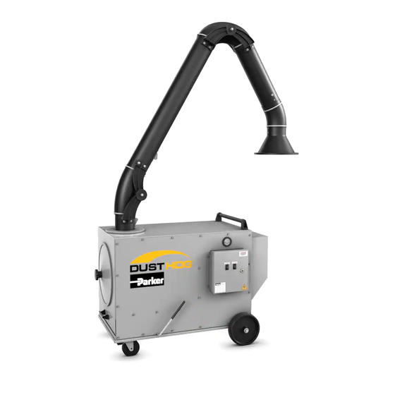
3. Portable Unit w/ Swing Arm (VP) airborne particles as they are generated. Contaminant There are two primary cycles of normal operation for the V Series Within these variations, the units have two different — the air filtering operation and the filter cleaning cycle utilizing a is captured at its source by a unit-mounted hood, models, the 750 and the 1500. -
Page 9: Installation
4.2.1 Portable Installation (VP Model) Figure 2. Swing Arm Installation Detail The top of the V Series cabinet has either one set of six (VP-750) or eight (VP-1500) threaded studs to mount the swing arm. The neces- sary hardware is pre-assembled the studs. When mounting the arms on the unit, a ceiling height of about 10’... -
Page 10: Fixed Unit Assembly (Vf Model)
Number of downtime pulses performed upon blower shutdown: Length of time between pulses: 10 or 30 seconds If your V Series system came with a cleaning system, please review 1, 2, 4 or 6 the following section for optimum performance. -
Page 11: Operation
Access the unit to push the V Series into the desired location. After the unit is motor starter leads should be reversed if the should be restricted to qualified personnel. -
Page 12: Service
6.2 Dust Drawer Removal 1. To access and remove the dust drawer located at the base of the V Series unit, you must first unseal the drawer by pulling the drawer release handle (see Figure 8) toward the filter access side of the cabinet. -
Page 13: Electrical
7. Electrical Tables 1 and 2 provide a listing of V Series model numbers and their corresponding voltage, motor horsepower and full load amperage draw. Please complete the provided blanks on the inside cover of this manual. This will help you to identify your unit when dealing directly with Parker or your local Parker representative. -
Page 14: Troubleshooting
V SERIES Revised 08/09 Cartridge Dust Collector 8. TROUBLESHOOTING 8. Troubleshooting PROBLEM POSSIBLE CAUSE RECOMMENDED SOLUTIONS The Swing Arm slips from The joints require adjustment. Adjust the joints (refer to Section 8.2 of the set position. Swing Arm Manual) Strong resistance during Lack of grease in the rotating socket. - Page 17 Swing Arm, W/ Paravent Hood, 8” Dia. x 14’ Extension 17-0026 Caster Rigid, 5” Dia. 17-0027 Caster-Swivel, 5” Dia. w/ Lock 39-0268 Push Handle Bar Downdraft Bench V Series Replacement Parts Item Number Part Number General Description 10-11872-0001 Grate, Bench, VS1500 10-11873-0001...
-
Page 18: Appendix
Revised 08/09 V SERIES Revised 08/09 Cartridge Dust Collector Cartridge Dust Collector Cartridge Dust Collector Appendix A. V Series Wiring Diagram APPENDIX A. V SERIES WRING DIAGRAM APPENDIX A. V SERIES WRING DIAGRAM APPENDIX A. V SERIES WRING DIAGRAM 41-2537 41-2537 41-2537 Figure 10. - Page 19 V SERIES V SERIES Revised 08/09 Revised 08/09 Cartridge Dust Collector Cartridge Dust Collector 41-2542 41-2542 Figure 13. Wiring Diagram 230 Volt, Single Phase, Pulse Cleaning Figure 13. Wiring Diagram 230 Volt, Single Phase, Pulse Cleaning Figure 13. Wiring Diagram 230 Volt, Single Phase, Pulse Cleaning...
- Page 20 41-2544 Figure 15. Wiring Diagram, Three Phase, Pulse Cleaning w/ UAS Supplied Starter 41-2544 Figure 15. Wiring Diagram, Three Phase, Pulse Cleaning w/ Parker Supplied Starter Figure 15. Wiring Diagram, Three Phase, Pulse Cleaning w/ UAS Supplied Starter 41-2544 Figure 15. Wiring Diagram, Three Phase, Pulse Cleaning w/ UAS Supplied Starter 41-2545 Figure 16.
-
Page 21: Equipment Warranty
Page intentionally left blank... - Page 22 MCB, PNP, SDC, SFC, and SHM series will be free from defects in materials and workmanship for ten (10) years from the date of shipment from Parker. Subject to the terms and conditions hereof, warrants to the original...
- Page 23 On claims that require repaired parts return, the claim will be processed after the part has been evaluated by the Parker IGFG Quality Department for verification of failure mode. The claims will be paid in the form of a credit to the customer’s account.
- Page 24 310 637 3400 +44 (0) 191 410 5121 +27 11 9610700 www.parker.com/watermakers www.parker.com/processfiltration www.parker.com/africa © 2020 Parker Hannifin Corporation. Product names are trademarks or registered trademarks of their respective companies MAN-IOU-VSeries-122020 P/N: 44-10448-0001 Parker Hannifin Corporation Industrial Gas Filtration and Generation Division...
Need help?
Do you have a question about the V Series and is the answer not in the manual?
Questions and answers