
Related Manuals for Inxpect LBK System


Summary of Contents for Inxpect LBK System
- Page 1 LBK System LBK System BUS SBV System BUS SRE - Safety Radar Equipment Istruzioni per l’installazione Installation instructions Installationsanleitung v2.0 - IT / EN / DE...
-
Page 2: Avvertenze Generali
Mantenere sgombro il campo visivo del sensore. Conformità CE Il fabbricante, Inxpect SpA, dichiara che l'apparecchiatura radio di tipo LBK System è conforme alle direttive 2014/53/UE e 2006/42/CE. Il testo completo della dichiarazione di conformità UE è... - Page 3 Descrizione Porta micro-USB per collegare il PC e comunicare con l'applicazione Inxpect Safety Porta micro-USB (riservata) LED stato Fieldbus (Ethernet) Porta Ethernet con LED per collegare il PC e comunicare con l'applicazione Inxpect Safety Morsettiera alimentazione LED alimentazione (verde fisso)
- Page 4 Sensore in funzione. Nessun movimento rilevato. Blu lampeggiante Il sensore sta rilevando un movimento. Non disponibile se il sensore è in muting. Viola Condizioni di aggiornamento del firmware Rosso Condizioni di errore Istruzioni per l'installazione SAF-MI-LBK-SBV-multi-v2.0-print-26000041 | © 2020-2021 Inxpect SpA...
- Page 5 Schermatura, da collegare a terra sulla morsettiera di alimentazione dell'unità di controllo. + 12 V cc CAN H CAN L Morsettiera uscite di sicurezza LBK-C22 Simbolo Descrizione Comune uscita sicurezza 1 Uscita relè normalmente aperto SAF-MI-LBK-SBV-multi-v2.0-print-26000041 | © 2020-2021 Inxpect SpA Istruzioni per l'installazione...
- Page 6 Nota: i cavi usati devono avere una lunghezza massima di 30 m e una temperatura di esercizio di almeno 90 °C. Nota: usare solo fili in rame con sezione minima di 18 AWG e coppia di serraggio di 0,56 Nm. Istruzioni per l'installazione SAF-MI-LBK-SBV-multi-v2.0-print-26000041 | © 2020-2021 Inxpect SpA...
- Page 7 Nota: i cavi usati devono avere una lunghezza massima di 30 m e devono avere una temperatura di esercizio di almeno 80 °C. Nota: usare solo fili in rame con sezione minima di 18 AWG e coppia di serraggio di 0,62 Nm. SAF-MI-LBK-SBV-multi-v2.0-print-26000041 | © 2020-2021 Inxpect SpA Istruzioni per l'installazione...
- Page 8 Nota: i cavi devono avere una temperatura di esercizio di almeno 70 °C. Nota: usare solo fili in rame con sezione minima di 18 AWG e coppia di serraggio di 0,62 Nm. Istruzioni per l'installazione SAF-MI-LBK-SBV-multi-v2.0-print-26000041 | © 2020-2021 Inxpect SpA...
-
Page 9: Installazione
6. Selezionare il dispositivo (LBK System BUS o SBV System BUS). 7. (Solo per LBK System BUS) Impostare la frequenza di lavoro. Se il sistema è installato in uno dei paesi con restrizioni nazionali, selezionare la banda ristretta, altrimenti selezionare la banda completa. - Page 10 1. Avviare l'applicazione. 2. Per LBK System fare clic su Login e Configurazione. Per LBK System BUS e SBV System BUS, fare clic su User > Configurazione. 3. Definire l'area da monitorare e la configurazione dei sensori.
- Page 11 Esempi di catene). 2. Avviare l'applicazione. 3. Per LBK System fare clic su Login e Configurazione. Per LBK System BUS fare clic su User > Configurazione. 4. Verificare che il numero di sensori inclusi nella configurazione sia uguale a quello dei sensori installati.
- Page 12 Manuale: per assegnare il Node ID a un sensore alla volta. Può essere eseguita per tutti i sensori già collegati o dopo ciascun collegamento. È utile per aggiungere un sensore o per modificare il Istruzioni per l'installazione SAF-MI-LBK-SBV-multi-v2.0-print-26000041 | © 2020-2021 Inxpect SpA...
- Page 13 4. Richiedere la firma della persona autorizzata. Richiedere la firma della persona autorizzata. Cosa fare dopo Seguire le istruzioni del manuale per validare le funzioni di sicurezza e gestire la configurazione. www.inxpect.com/industrial/tools SAF-MI-LBK-SBV-multi-v2.0-print-26000041 | © 2020-2021 Inxpect SpA Istruzioni per l'installazione...
-
Page 14: Component Structure
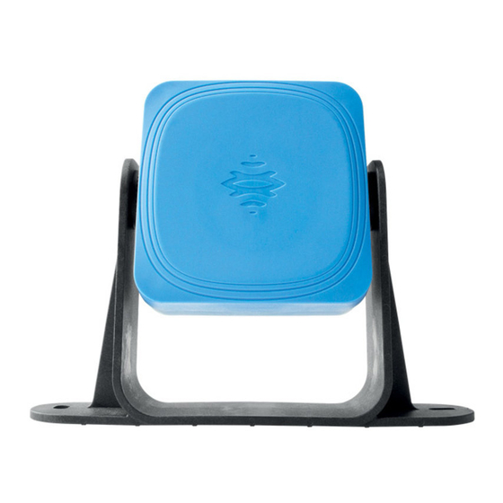
Keep the sensor field of view unobstructed. CE Conformity The manufacturer, Inxpect SpA, states that LBK System type of radio equipment complies with the 2014/53/EU and 2006/42/CE directives. The manufacturer, Inxpect SpA, states that LBK System SRE (Safety Radar Equipment) complies with the 2014/53/EU and 2006/42/CE directives. - Page 15 Digital input High logic level (1) LBK-S01 sensors Part Description Sensor Screws for fastening the sensor at a specific inclination Perforated bracket for installing the sensor on the ground or on the wall SAF-MI-LBK-SBV-multi-v2.0-print-26000041 | © 2020-2021 Inxpect SpA Installation instructions...
- Page 16 SBV-01 status LED Status Meaning Steady blue Sensor is working. No motion detected. Flashing blue Sensor is detecting motion. Not available if the sensor is in muting. Purple Firmware update conditions Error conditions Installation instructions SAF-MI-LBK-SBV-multi-v2.0-print-26000041 | © 2020-2021 Inxpect SpA...
- Page 17 LBK-C22 and ISC-B01 M12 CAN bus connectors Male connector Female connector Function Shield, to be connected to earth circuit power supply terminal block of the controller. + 12 V dc CAN H CAN L SAF-MI-LBK-SBV-multi-v2.0-print-26000041 | © 2020-2021 Inxpect SpA Installation instructions...
- Page 18 Note: the operating temperature of the cables must be at least 80 °C. Note: use only copper wires with a minimum gauge of 18 AWG and a torque of 0.56 Nm (5 lbs in). Installation instructions SAF-MI-LBK-SBV-multi-v2.0-print-26000041 | © 2020-2021 Inxpect SpA...
- Page 19 Note: the operating temperature of the cables must be at least 80 °C. Note: use only copper wires with a minimum gauge of 18 AWG and a torque of 0.56 Nm (5 lbs in). SAF-MI-LBK-SBV-multi-v2.0-print-26000041 | © 2020-2021 Inxpect SpA Installation instructions...
- Page 20 Note: the operating temperature of the cables must be at least 70 °C. Note: use only copper wires with a minimum gauge of 18 AWG and a torque of 0.62 Nm (5,5 lbs in). Installation instructions SAF-MI-LBK-SBV-multi-v2.0-print-26000041 | © 2020-2021 Inxpect SpA...
-
Page 21: Installation
6. Select the device (LBK System BUS or SBV System BUS). 7. (only for LBK System BUS) Set the working frequency. If the system is installed in one of the countries with national restrictions, select the restricted band, otherwise select the full band. - Page 22 Start the application. 2. For LBK System, click Login and Configuration. For LBK System BUS and for SBV System BUS, click User and Configuration. 3. Define the area to be monitored and the sensor configuration.
- Page 23 Configuration. 4. Verify that the number of sensors in the configuration is the same of the sensors installed. 5. For LBK System, click Settings and Sensor ID Nodes. For LBK System BUS, click Settings and Node ID Assignment. 6. Set the DIP switch of the controller based on its position in the chain.
- Page 24 Automatic: to assign the Node IDs to all sensors at once. To be performed when all the sensors are connected. Semi-automatic: wizard for connecting the sensors and assign the Node ID one sensor at a time. Installation instructions SAF-MI-LBK-SBV-multi-v2.0-print-26000041 | © 2020-2021 Inxpect SpA...
- Page 25 4. Require a signature by the authorized person.Ask the authorized person for a signature. What to do next Follow the instructions in the manual to validate the safety functions and manage the configuration. www.inxpect.com/industrial/tools SAF-MI-LBK-SBV-multi-v2.0-print-26000041 | © 2020-2021 Inxpect SpA Installation instructions...
- Page 26 Sichtfeld des Sensors frei von Objekten gehalten werden. EG-Konformität Der Hersteller Inxpect SpA erklärt hiermit, dass der Funkanlagentyp LBK System den Vorgaben der Richtlinien 2014/53/EU und 2006/42/EG entspricht. Die vollständige EU-Konformitätserklärung ist über die folgende Website abrufbar: www.inxpect.com.
- Page 27 Anwendung Inxpect Safety Micro-USB-Anschluss (reserviert) Zustands-LED Feldbus (Ethernet) Ethernet-Anschluss mit LED für die Verbindung mit dem PC und die Kommunikation mit der Anwendung Inxpect Safety Anschlussleiste Spannungsversorgung LEDs der Spannungsversorgung (Grün, Dauerlicht) CAN-Bus-Anschlussleiste für den Anschluss des ersten Sensors DIP-Schalter zum Einschalten/Ausschalten des Busabschlusses: On (Standard) = Widerstand eingeschaltet...
- Page 28 Zustands-LED SBV-01 Zustand Bedeutung Blau, Dauerlicht Sensor in Betrieb. Keine Bewegung erfasst. Blau blinkend Der Sensor erfasst gerade eine Bewegung. Nicht verfügbar, wenn der Sensor auf Muting geschaltet ist. Violett Die Firmware wird aktualisiert Fehlerzustand Installationsanleitung SAF-MI-LBK-SBV-multi-v2.0-print-26000041 | © 2020-2021 Inxpect SpA...
- Page 29 M12-Steckverbinder für CAN-Bus LBK-C22 und ISC-B01 Stecker Buchse Funktion Abschirmung, zu erden an der Versorgungsklemme der Steuerungseinheit. + 12 V DC CAN H CAN L Anschlussleiste Sicherheitsausgänge LBK-C22 Symbol Beschreibung Gemeinsamer Sicherheitsausgang 1 Relaisausgang normalerweise offen SAF-MI-LBK-SBV-multi-v2.0-print-26000041 | © 2020-2021 Inxpect SpA Installationsanleitung...
- Page 30 Eingang 24 V DC Diagnose Gemeinsames Bezugspotenzial für alle Digitaleingänge Info: Die verwendeten Kabel dürfen max. 30 m lang sein und müssen eine Betriebstemperatur von mindestens 90 °C haben. Info: Nur Kupferdrähte mit Mindestquerschnitt 18 AWG und Anziehdrehmoment 0,56 Nm verwenden. Installationsanleitung SAF-MI-LBK-SBV-multi-v2.0-print-26000041 | © 2020-2021 Inxpect SpA...
- Page 31 Ausgang 1 (OSSD1) GND, gemeinsames Bezugspotenzial für alle Digitalausgänge Info: Die verwendeten Kabel dürfen max. 30 m lang sein und müssen eine Betriebstemperatur von mindestens 80 °C haben. Info: Nur Kupferdrähte mit Mindestquerschnitt 18 AWG und Anziehdrehmoment 0,62 Nm verwenden. SAF-MI-LBK-SBV-multi-v2.0-print-26000041 | © 2020-2021 Inxpect SpA Installationsanleitung...
- Page 32 Anschlussleiste Spannungsversorgung ISC-B01 Info: Vorderansicht Stecker. Symbol Beschreibung Erde + 24 V DC Info: Die Kabel müssen eine Betriebstemperatur von mindestens 70 °C haben. Info: Nur Kupferdrähte mit Mindestquerschnitt 18 AWG und Anziehdrehmoment 0,62 Nm verwenden. Installationsanleitung SAF-MI-LBK-SBV-multi-v2.0-print-26000041 | © 2020-2021 Inxpect SpA...
- Page 33 Änderung der Konfiguration befugt sind. 6. Das Gerät (LBK System BUS oder SBV System BUS) auswählen. 7. (Nur für LBK System BUS) Die Arbeitsfrequenz festlegen. Wenn das System in einem Land installiert wird, in dem nationale Beschränkungen gelten, den eingeschränkten Frequenzbereich auswählen.
- Page 34 Systems geeignete Sicherheitsmaßnahmen in dem durch das System geschützten Gefahrenbereich treffen. 1. Die Anwendung starten. 2. Für LBK System auf Login und Konfiguration klicken. Für LBK System BUS und SBV System BUS auf User > Konfiguration klicken. 3. Den Überwachungsbereich und die Konfiguration der Sensoren festlegen.
- Page 35 (siehe Beispiele für Ketten). 2. Die Anwendung starten. 3. Für LBK System auf Login und Konfiguration klicken. Für LBK System BUS auf User > Konfiguration klicken. 4. Prüfen, ob die Anzahl der in der Konfiguration enthaltenen Sensoren der Anzahl der installierten Sensoren entspricht.
- Page 36 3. Den gewünschten Sensor direkt an der Steuerungseinheit anschließen. 4. Den Busabschluss (Art.-Nr. 07000003) in den freien Stecker des Sensors stecken. 5. Zum Anschließen eines anderen Sensors den Sensor direkt an der Steuerungseinheit oder am letzten Sensor der Kette anschließen. Installationsanleitung SAF-MI-LBK-SBV-multi-v2.0-print-26000041 | © 2020-2021 Inxpect SpA...
- Page 37 Auf NODE-ID ZUWEISEN > Halbautomatisch klicken und den angezeigten Anweisungen folgen. Beispiele für Ketten Kette mit Steuerungseinheit am Kettenende und einem Kette mit Steuerungseinheit innerhalb der Kette und zwei Sensor mit Abschlussstecker Sensoren mit Abschlussstecker SAF-MI-LBK-SBV-multi-v2.0-print-26000041 | © 2020-2021 Inxpect SpA Installationsanleitung...
- Page 38 4. Die Unterschrift der befugten Person einholen. Die Unterschrift der befugten Person einholen. Was als Nächstes zu tun ist Für die Prüfung der Sicherheitsfunktionen und die Verwaltung der Konfiguration sind die Anweisungen in diesem Handbuch zu befolgen. www.inxpect.com/industrial/tools Installationsanleitung SAF-MI-LBK-SBV-multi-v2.0-print-26000041 | © 2020-2021 Inxpect SpA...
- Page 39 SAF-MI-LBK-SBV-multi-v2.0-print-26000041 | © 2020-2021 Inxpect SpA...
- Page 40 SAF-MI-LBK-SBV-multi-v2.0-print-26000041 | © 2020-2021 Inxpect SpA...
- Page 41 SAF-MI-LBK-SBV-multi-v2.0-print-26000041 | © 2020-2021 Inxpect SpA...
- Page 42 SAF-MI-LBK-SBV-multi-v2.0-print-26000041 | © 2020-2021 Inxpect SpA...
- Page 43 SAF-MI-LBK-SBV-multi-v2.0-print-26000041 | © 2020-2021 Inxpect SpA...
- Page 44 LBK System BUS and SBV System BUS LBK System LBK System BUS and SBV System BUS LBK System SAF-MI-LBK-SBV-multi-v2.0-print-26000041 | © 2020-2021 Inxpect SpA...
- Page 48 Designed, engineered and manufactured in Italy by Inxpect SpA Via Serpente, 91 25131 Brescia (BS)Italy www.inxpect.com safety-support@inxpect.com LBK System, LBK System BUS, SBV System BUS +39 030 5785105 SAF-MI-LBK-SBV-multi-v2.0-print-26000041 RMA Service Request © 2020-2021 Inxpect SpA www.inxpect.com/industrial/rma...
Need help?
Do you have a question about the LBK System and is the answer not in the manual?
Questions and answers