Table of Contents
Advertisement
Quick Links
Advertisement
Table of Contents

Related Manuals for Inxpect LBK System BUS


Summary of Contents for Inxpect LBK System BUS
- Page 1 LBK System BUS SRE - Safety Radar Equipment Instruction manual v1.0 - EN Original instructions WARNING! Any who uses this system must read the instruction manual to ensure safety. Read and adhere to the "Safety information" chapter in its entirety before using the system for the first...
- Page 2 Transferring the document on websites or other electronic systems. Copying contents without any modification and stating Inxpect SpA as copyright owner. Inxpect SpA reserves the right to make modifications or improvements to the relative documentation without prior notice. Requests for authorizations, additional copies of this manual or technical...
-
Page 3: Table Of Contents
8. Technical references 8.1 Technical data 8.2 Terminal blocks and connector pin-outs 8.3 Electrical connections 8.4 Parameters 8.5 Digital input signals 9. Appendix 9.1 Disposal 9.2 Service and warranty LBK System BUS | Instruction manual v1.0 SEP 2020 | LBK-System-BUS_instructions_en v1.0 | © 2020 Inxpect SpA... -
Page 4: Glossary Of Terms
Detection signal 1 Output signal that describes the monitoring status of detection field 1. Detection signal 2 Output signal that describes the monitoring status of detection field 2. LBK System BUS | Instruction manual v1.0 SEP 2020 | LBK-System-BUS_instructions_en v1.0 | © 2020 Inxpect SpA... - Page 5 Output Signal Switching Device Tolerance area Area of the field of view where detection or not of an object depends on the characteristics of the same object. LBK System BUS | Instruction manual v1.0 SEP 2020 | LBK-System-BUS_instructions_en v1.0 | © 2020 Inxpect SpA...
-
Page 6: This Manual
This manual explains how to integrate LBK System BUS for safeguarding machinery operators and how to install it, use it and maintain it safely. The functioning and safety of the machinery to which LBK System BUS is connected is out of the scope of this document. -
Page 7: Safety
2.1.4 INTENDED USE LBK System BUS is certified SIL 2 according to IEC/EN 62061 and PL d in accordance with EN ISO 13849-1. Performs the following safety functions: access detection function: prevents access to a dangerous area. Access to the area deactivates the safety outputs to stop the moving parts of the machinery. - Page 8 The system does not offer protection from pieces ejected from the machinery, from radiation, and objects falling from above. The machinery command must be electronically controlled. LBK System BUS | Instruction manual v1.0 SEP 2020 | LBK-System-BUS_instructions_en v1.0 | © 2020 Inxpect SpA...
-
Page 9: Conformity
2.3 National restrictions 2.3.1 FRANCE AND THE UNITED KINGDOM LBK System BUS is a short-range device in class 2 in accordance with the directive 2014/53/EU (RED - Radio equipment) and is subject to the following restrictions: Restrictions in UK. In the United Kingdom, the national allocation of frequencies does not allow the free use of the whole band 24-24.25 GHz. - Page 10 Restrictions in South Korea. In South Korea, the national allocation of frequencies does not allow the free use of the whole band 24-24.25 GHz. Set the country correctly in the Inxpect Safety application and the authorized band 24.05-24.25 GHz will be automatically selected.
-
Page 11: Get To Know Lbk System Bus
Serial number 3.1 LBK System BUS 3.1.1 Definition LBK System BUS is an active protection radar system that monitors the dangerous areas of machinery. 3.1.2 Special features Some of the special features of this protection system are the following: immunity to dust and smoke reduction of undesired alarms caused by the presence of water or processing waste possibility to configure a second safe detection field (e.g. - Page 12 LBK System BUS deactivates the safety outputs and keeps them deactivated, so the control system can put the area into a safe condition and/or prevent restarting of the machinery. In the absence of other control systems, LBK System BUS can be connected to the devices that control the power supply or machinery start-up.
-
Page 13: Controller Isc-B01
Micro-USB port for connecting the PC and communicating with the Inxpect Safety application Micro-USB port (reserved) Fieldbus status LEDs (Ethernet) Ethernet port with LEDs for connecting the PC and communicating with the Inxpect Safety application Power supply terminal block Error LEDs... - Page 14 The function of each digital input must be programmed through the Inxpect Safety application. The available functions are the following: Stop signal: manages a specific signal to force all the safety outputs (detection signal 1 and detection signal 2, if present) to OFF-state.
- Page 15 (e.g. system diagnostic, muting enable feedback and two Fieldbus controlled outputs). The dual channel safety output is automatically obtained by the Inxpect Safety application and it matches the single OSSD outputs only as follows:...
-
Page 16: Sensors Lbk-S01
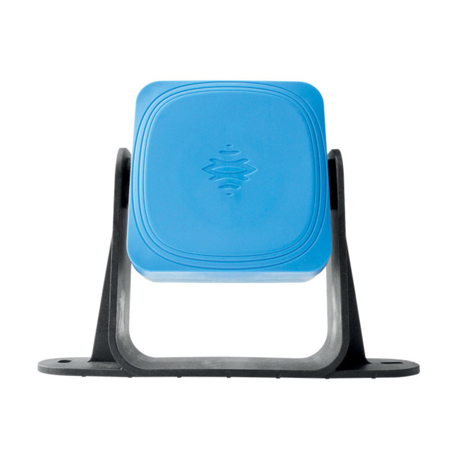
Perforated bracket for installing the sensor on the ground or on the machinery Status LED Connectors for connecting the sensors in a chain and to the controller LBK System BUS | Instruction manual v1.0 SEP 2020 | LBK-System-BUS_instructions_en v1.0 | © 2020 Inxpect SpA... -
Page 17: Inxpect Safety Application
Check system functioning. Download system log. WARNING! The Inxpect Safety application must be used only for the system configuration and for the first validation. It cannot be used for monitoring the system continuously during the regular operation of the machinery. -
Page 18: Fieldbus Communication
3.5.3 Data exchanged through Fieldbus The following table details the data exchanged through the Fieldbus communication: LBK System BUS | Instruction manual v1.0 SEP 2020 | LBK-System-BUS_instructions_en v1.0 | © 2020 Inxpect SpA... -
Page 19: System Configuration
3.6 System configuration 3.6.1 System configuration The controller parameters have their own default values that can be modified via the Inxpect Safety application (see "Parameters" on page 74). 3.6.2 Dynamic system configuration LBK System BUS allows a real-time adjustment of the most important system parameters, providing the means to switch dynamically among different preset configurations. - Page 20 Ethernet cable. The USB cable allows to configure the system locally, whereas the Ethernet cable allows to do it remotely. The Ethernet communication between the ISC-B01 and the Inxpect Safety application is secured by the most advanced security protocols (TLS).
- Page 21 If the activation is set for both the digital inputs and the safety Fieldbus, LBK System BUS uses the digital input data and ignores the dynamic changes made through the safety Fieldbus.
-
Page 22: Functioning Principles
Each sensor has its own fieldset. The fieldset corresponds to the structure of the field of view, which can be composed of one or two detection fields. Detection field examples Angular coverage Detection fields 110° 50° LBK System BUS | Instruction manual v1.0 SEP 2020 | LBK-System-BUS_instructions_en v1.0 | © 2020 Inxpect SpA... - Page 23 All these factors have been analyzed during the safety validation of LBK System BUS and cannot lead to a dangerous situation. These factors may occasionally influence the behavior of the system causing spurious activation of the safety function.
- Page 24 3 equivalent architecture: Sensors belonging to each pair that are installed on two different heights and have the same detection LBK System BUS | Instruction manual v1.0 SEP 2020 | LBK-System-BUS_instructions_en v1.0 | © 2020 Inxpect SpA...
-
Page 25: Safety Working Modes And Safety Functions
Restart prevention The machinery is prevented from restarting if people are in the dangerous area. 4.3.2 Safety working modes Via the Inxpect Safety application, you can select which safety working mode each sensor will perform for each of its detection fields:... - Page 26 2 remains active and switches to is deactivated and switches to the restart prevention function the restart prevention function LBK System BUS | Instruction manual v1.0 SEP 2020 | LBK-System-BUS_instructions_en v1.0 | © 2020 Inxpect SpA...
- Page 27 2 remains active and switches to is deactivated and remains in the access prevention function the access prevention function LBK System BUS | Instruction manual v1.0 SEP 2020 | LBK-System-BUS_instructions_en v1.0 | © 2020 Inxpect SpA...
- Page 28 2 remains active and in the is deactivated and remains in access prevention function the access prevention function LBK System BUS | Instruction manual v1.0 SEP 2020 | LBK-System-BUS_instructions_en v1.0 | © 2020 Inxpect SpA...
-
Page 29: Safety Working Mode: Both (Default)
WARNING! When the restart prevention function is active all the sensors have a 110° angular coverage, regardless of the angular coverage set. LBK System BUS | Instruction manual v1.0 SEP 2020 | LBK-System-BUS_instructions_en v1.0 | © 2020 Inxpect SpA... -
Page 30: Safety Working Mode: Always Access Detection
[A], lying down [B] or leaning [C]. LBK System BUS | Instruction manual v1.0 SEP 2020 | LBK-System-BUS_instructions_en v1.0 | © 2020 Inxpect SpA... - Page 31 Only when there are no restrictions does the function ensure that a person is detected when standing up [D]. LBK System BUS | Instruction manual v1.0 SEP 2020 | LBK-System-BUS_instructions_en v1.0 | © 2020 Inxpect SpA...
-
Page 32: Muting
See "Configure the inputs and outputs" on page 49. LBK System BUS | Instruction manual v1.0 SEP 2020 | LBK-System-BUS_instructions_en v1.0 | © 2020 Inxpect SpA... -
Page 33: Anti-Tampering Functions: Anti-Rotation Around Axes (Accelerometer)
The muting function is enabled only if both logic signals of the dedicated input meet certain characteristics. Below is a graphic representation of the signal characteristics. In the Inxpect Safety application, in Configuration > Settings > Digital Input-Output it is necessary to set the parameters that define the characteristics of the signal. -
Page 34: Anti-Tampering Functions: Anti-Masking
See "Checks when the anti-rotation around axes function is disabled" below. In the Inxpect Safety application, in Configuration > Settings click Sensors to disable the anti-rotation around axes function. -
Page 35: Multi-Controller Synchronization
See "Checks when the anti-masking function is disabled" below. To change the sensitivity level or disable the function, in the Inxpect Safety application click Configuration > Settings and then Sensors. 4.10.6 Checks when the anti-masking function is disabled When the anti-masking function is disabled, perform the following checks. - Page 36 1. In the Inxpect Safety application click Configuration > Settings > Digital Input-Output. 2. Associate one of the digital inputs of each ISC-B01 controller to Acquisition Trigger. LBK System BUS | Instruction manual v1.0 SEP 2020 | LBK-System-BUS_instructions_en v1.0 | © 2020 Inxpect SpA...
-
Page 37: Sensor Position
Three examples are presented as follows: sensor tilted upwards: α positive straight sensor: α = 0 sensor tilted downwards: α negative LBK System BUS | Instruction manual v1.0 SEP 2020 | LBK-System-BUS_instructions_en v1.0 | © 2020 Inxpect SpA... -
Page 38: Sensor Field Of View
"Factors that influence the reflected signal" on page 23). Dimensions of the 110° field of view Side view Top view Dimensions of the 50° field of view Side view Top view LBK System BUS | Instruction manual v1.0 SEP 2020 | LBK-System-BUS_instructions_en v1.0 | © 2020 Inxpect SpA... -
Page 39: Dangerous Area Calculation
5.3 Dangerous area calculation 5.3.1 Introduction The dangerous area of the machinery to which LBK System BUS is applied must be calculated as indicated in standards ISO 13855:2010 and ISO 13857:2008. For LBK System BUS the fundamental factors for calculation are height (h) and inclination (α) of the sensor, see "Sensor position"... -
Page 40: Calculation Of Position For Sensor Height ≤ 1 M
3 = Configuration 3: the upper portion and the bottom portion of the field of view always intersect the ground X = Configuration not possible WARNING! With configurations not listed in these tables or marked with an “x”, safety functions are not guaranteed. LBK System BUS | Instruction manual v1.0 SEP 2020 | LBK-System-BUS_instructions_en v1.0 | © 2020 Inxpect SpA... - Page 41 Distance between the ground and the field of view of the sensor α Sensor inclination degrees Sensor installation height Dalarm Detection distance (linear) DalarmReal Detection distance (real) Start detection distance End detection distance LBK System BUS | Instruction manual v1.0 SEP 2020 | LBK-System-BUS_instructions_en v1.0 | © 2020 Inxpect SpA...
- Page 42 In this configuration, the field of view of the sensor never intersects the ground. To guarantee that the sensor also detects access by people crawling, respect the following condition: 110° field of view 50° field of view LBK System BUS | Instruction manual v1.0 SEP 2020 | LBK-System-BUS_instructions_en v1.0 | © 2020 Inxpect SpA...
- Page 43 To guarantee that the sensor also detects the presence of people crawling near the sensor, respect the following condition: 110° field of view 50° field of view LBK System BUS | Instruction manual v1.0 SEP 2020 | LBK-System-BUS_instructions_en v1.0 | © 2020 Inxpect SpA...
- Page 44 50° field of view 5.4.7 Calculate the real detection distance The actual detection distance DalarmReal is the value to be entered in the Configuration page of the Inxpect Safety application. DalarmReal indicates the maximum distance between the sensor and the object to be detected.
-
Page 45: Calculation Of Position For Sensor Height > 1 M
WARNING! It is only possible through the validation procedure (see "Validate the safety functions" on page 54) to check if the other configurations respect the performance levels required by the application. LBK System BUS | Instruction manual v1.0 SEP 2020 | LBK-System-BUS_instructions_en v1.0 | © 2020 Inxpect SpA... -
Page 46: Outdoor Installations
5. Sensor position 5.5.5 Calculate the real detection distance The actual detection distance DalarmReal is the value to be entered in the Configuration page of the Inxpect Safety application. DalarmReal indicates the maximum distance between the sensor and the object to be detected. - Page 47 5.6.4 Position not exposed to precipitation If the installation position of the sensor is not exposed to precipitation, no special precautions are required. LBK System BUS | Instruction manual v1.0 SEP 2020 | LBK-System-BUS_instructions_en v1.0 | © 2020 Inxpect SpA...
-
Page 48: Installation And Use Procedures
Note: connect the sensors to the controller off-site if access to the connectors becomes difficult once they are installed. 9. "Save and print the configuration" on page 53. LBK System BUS | Instruction manual v1.0 SEP 2020 | LBK-System-BUS_instructions_en v1.0 | © 2020 Inxpect SpA... -
Page 49: Install And Configure Lbk System Bus
3. If the muting is managed, click Muting and assign the sensors to the groups according to the logic of the digital inputs. 4. Click APPLY CHANGES to save the configuration. LBK System BUS | Instruction manual v1.0 SEP 2020 | LBK-System-BUS_instructions_en v1.0 | © 2020 Inxpect SpA... - Page 50 3. Direct the sensor up to the desired inclination, 4. Tighten the screws. see "Sensor position" on page 37. Note: a notch is equal to 10° of inclination. LBK System BUS | Instruction manual v1.0 SEP 2020 | LBK-System-BUS_instructions_en v1.0 | © 2020 Inxpect SpA...
- Page 51 4. Direct the sensor up to the desired inclination, support. see "Sensor position" on page 37. Note: a notch is equal to 10° of inclination. 5. Tighten the screws. LBK System BUS | Instruction manual v1.0 SEP 2020 | LBK-System-BUS_instructions_en v1.0 | © 2020 Inxpect SpA...
- Page 52 Note: the maximum length of the CAN bus line from the controller to the last sensor of the chain is 30 m. 5. Insert the bus terminator (product code: 07000003) into the free connector of the sensor/sensors at the end of the chain by performing the following steps: LBK System BUS | Instruction manual v1.0 SEP 2020 | LBK-System-BUS_instructions_en v1.0 | © 2020 Inxpect SpA...
- Page 53 Chain with controller inside of the chain and two sensors with bus terminator 6.2.9 Save and print the configuration 1. In the Inxpect Safety application, click APPLY CHANGES: the sensors will memorize the inclination set and the surrounding environment. The application will transfer the configuration to the controller, and once transfer is complete it will generate a configuration report.
-
Page 54: Validate The Safety Functions
Stop in several different points, with special attention to the areas in close proximity to the sensor and any blind spots, see "Example of stopping points" below. Stop standing as well as laid down. LBK System BUS | Instruction manual v1.0 SEP 2020 | LBK-System-BUS_instructions_en v1.0 | © 2020 Inxpect SpA... - Page 55 WARNING! When the validation function is active, the system response time is not guaranteed. The Inxpect Safety application is helpful during the safety functions validation phase and allows the actual field of view of the sensors to be checked based on their installation position.
-
Page 56: Manage The Configuration
Note: a re-imported configuration requires new downloading onto the controller and approval according to the safety plan. 6.4.5 Display previous configurations In Settings, click Activity History and then click Configuration reports page: the reports archive opens. In Configuration click . LBK System BUS | Instruction manual v1.0 SEP 2020 | LBK-System-BUS_instructions_en v1.0 | © 2020 Inxpect SpA... -
Page 57: Other Functions
In Configuration > Settings > Network Parameters change the IP address, the netmask and the gateway of the controller as desired. 6.5.7 Change Fieldbus parameters In Configuration > Settings > Fieldbus Parameters change the First F-Dest-Addr of the controller. LBK System BUS | Instruction manual v1.0 SEP 2020 | LBK-System-BUS_instructions_en v1.0 | © 2020 Inxpect SpA... -
Page 58: Maintenance And Troubleshooting
7. Maintenance and troubleshooting Machinery maintenance technician The machinery maintenance technician is a qualified person, with the administrator privileges required to modify the configuration of the LBK System BUS through the software and perform maintenance. Contents This section includes the following topics: 7.1 Troubleshooting... - Page 59 Check the status of the LEDs on the sensor, see "Sensor LED" on the previous page. Access the application Inxpect Safety, in the Dashboard page, click in correspondence with the controller or the sensor. LBK System BUS | Instruction manual v1.0 SEP 2020 | LBK-System-BUS_instructions_en v1.0 | © 2020 Inxpect SpA...
-
Page 60: System Log
Packet control code does not match COMMUNICATION Impossible to communicate with the sensor LOST PROTOCOL ERROR Controller and sensors have different and incompatible firmware versions POLLING TIMEOUT Timeout on data polling LBK System BUS | Instruction manual v1.0 SEP 2020 | LBK-System-BUS_instructions_en v1.0 | © 2020 Inxpect SpA... - Page 61 Indicates that the system must still be configured. This message can appear when the system is first turned on or after reset to default values. It can also represent another error on the FEE (internal memory). LBK System BUS | Instruction manual v1.0 SEP 2020 | LBK-System-BUS_instructions_en v1.0 | © 2020 Inxpect SpA...
- Page 62 Wrong CRC ERROR 7.2.11 System boot (SYSTEM BOOT) Each time LBK System BUS starts, a "SYSTEM BOOT" event is recorded with the incremental progressive number of the restart. The timestamp is reset to zero. 7.2.12 System safety alarm (SYSTEM SAFETY ALARM)
-
Page 63: Cleaning And Spare Parts
To download any firmware updates for the controller and the sensors, open the website www.inxpect.com/industrial/tools. 7.4.3 Install firmware updates (only if applicable) WARNING! During firmware update, LBK System BUS may not be fully operative. Make sure that the machinery is in safe conditions before installing updates. 1. Start the Inxpect Safety application. -
Page 64: Technical References
8. Technical references Contents This section includes the following topics: 8.1 Technical data 8.2 Terminal blocks and connector pin-outs 8.3 Electrical connections 8.4 Parameters 8.5 Digital input signals LBK System BUS | Instruction manual v1.0 SEP 2020 | LBK-System-BUS_instructions_en v1.0 | © 2020 Inxpect SpA... -
Page 65: Technical Data
National Electrical Code, NFPA 70, Default IP 192.168.0.20 and in the Canadian Electrical Code, C22.1. address Default TCP port Default 255.255.255.0 netmask Default 192.168.0.1 gateway LBK System BUS | Instruction manual v1.0 SEP 2020 | LBK-System-BUS_instructions_en v1.0 | © 2020 Inxpect SpA... - Page 66 From -40 to +80 °C temperature 10 mm 7.6 mm 2.2 mm Button head screws 10 mm 7.6 mm 2.2 mm min 1.3 mm 2.5 mm max 1.1 mm LBK System BUS | Instruction manual v1.0 SEP 2020 | LBK-System-BUS_instructions_en v1.0 | © 2020 Inxpect SpA...
-
Page 67: Terminal Blocks And Connector Pin-Outs
12 is the nearest to the Voltage limits controller corner. from - 3 to 11 V from 11 to 30 V Current limits 15 mA from 2 to 15 mA LBK System BUS | Instruction manual v1.0 SEP 2020 | LBK-System-BUS_instructions_en v1.0 | © 2020 Inxpect SpA... - Page 68 8.2.5 Connectors M12 CAN bus Male connector Female connector Function Shield, to be connected to earth circuit power supply terminal block of the controller. +12 V dc CAN H CAN L LBK System BUS | Instruction manual v1.0 SEP 2020 | LBK-System-BUS_instructions_en v1.0 | © 2020 Inxpect SpA...
-
Page 69: Electrical Connections
8. Technical references 8.3 Electrical connections 8.3.1 Connection of safety outputs to the machinery control system 8.3.2 Connection of safety outputs to an external safety relay LBK System BUS | Instruction manual v1.0 SEP 2020 | LBK-System-BUS_instructions_en v1.0 | © 2020 Inxpect SpA... - Page 70 Note: the indicated restart enable button closes the contact when pressed. Note: the cables used for wiring the digital inputs must have a maximum length of 30 m. LBK System BUS | Instruction manual v1.0 SEP 2020 | LBK-System-BUS_instructions_en v1.0 | © 2020 Inxpect SpA...
- Page 71 8.3.5 Connection of the muting input and output (one group of sensors) Note: the cables used for wiring the digital inputs must have a maximum length of 30 m. LBK System BUS | Instruction manual v1.0 SEP 2020 | LBK-System-BUS_instructions_en v1.0 | © 2020 Inxpect SpA...
- Page 72 8.3.6 Connection of the muting input and output (two groups of sensors) Note: the cables used for wiring the digital inputs must have a maximum length of 30 m. LBK System BUS | Instruction manual v1.0 SEP 2020 | LBK-System-BUS_instructions_en v1.0 | © 2020 Inxpect SpA...
- Page 73 8. Technical references 8.3.7 Detection signal 2 connection 8.3.8 Diagnostic output connection Note: the indicated light turns on in the presence of a failure. LBK System BUS | Instruction manual v1.0 SEP 2020 | LBK-System-BUS_instructions_en v1.0 | © 2020 Inxpect SpA...
-
Page 74: Parameters
Configuration > Sensors Operation Detection Distance 1(for 1000 mm 4000 mm 1500 mm each sensor) Detection Distance 2 (for 0 mm 3000 mm 500 mm each sensor) LBK System BUS | Instruction manual v1.0 SEP 2020 | LBK-System-BUS_instructions_en v1.0 | © 2020 Inxpect SpA... -
Page 75: Digital Input Signals
Period (for each Input TYPE) 200 ms 2000 ms 200 ms Phase shift (for each Input 0.4 ms 1000 ms 0.4 ms TYPE) 8.5 Digital input signals 8.5.1 Stop signal LBK System BUS | Instruction manual v1.0 SEP 2020 | LBK-System-BUS_instructions_en v1.0 | © 2020 Inxpect SpA... - Page 76 Minor than 50 ms. If the value is greater than 50 ms, the diagnostic alarm starts and the system deactivates the safety outputs. Activation delay. Minor than 2 ms. 8.5.2 Muting (with/without pulse) Without pulse With pulse LBK System BUS | Instruction manual v1.0 SEP 2020 | LBK-System-BUS_instructions_en v1.0 | © 2020 Inxpect SpA...
- Page 77 Activation delay. Minor than 200 ms. Diff Minor than 50 ms. If the value is greater than 50 ms, the diagnostic alarm starts and the system deactivates the safety outputs. LBK System BUS | Instruction manual v1.0 SEP 2020 | LBK-System-BUS_instructions_en v1.0 | © 2020 Inxpect SpA...
-
Page 78: Appendix
9.2 Service and warranty 9.1 Disposal LBK System BUS contains electrical parts. As set forth in European Directive 2012/19/EU, do not dispose of the product with unsorted urban waste materials. It is the responsibility of the owner to dispose of these products, as well as other electrical and electronic equipment, through specific waste collection facilities indicated by the government or local public authorities. - Page 80 Inxpect SpA Via Serpente, 91 LBK System BUS 25131 Brescia (BS) Instruction manual v1.0 Italy SEP 2020 www.inxpect.com LBK-System-BUS_instructions_en v1.0 safety-support@inxpect.com Copyright © 2020 Inxpect SpA +39 030 5785105...
Need help?
Do you have a question about the LBK System BUS and is the answer not in the manual?
Questions and answers