Table of Contents
Advertisement
Advertisement
Table of Contents

Subscribe to Our Youtube Channel
Related Manuals for Indutherm ROMANOFF VC480V


Summary of Contents for Indutherm ROMANOFF VC480V
- Page 1 9 Deforest street Amityville, NY, 11701 USA Romanoff.com Technical Documentation Vacuum-Pressure-Casting-Machine VC480V Romanoff order service for Romanoff consumables: technical service www.romanoff.com Tel.: +1-631-842-2400 service@romanoff.com Keep for future use!
- Page 2 16.10.2017 The manual is property of: INDUTHERM Erwärmungsanlagen GmbH Brettener Straße 32 D-75045 Walzbachtal Germany Tel.: + 49 7203 9218-0 Fax: + 49 7203 9218-70 E-Mail: info@indutherm.de Unauthorized duplication, even partial, is not permitted. Walzbachtal, 2017-10-16. sales@romanoff.com | romanoff.com...
-
Page 3: Table Of Contents
Contents Contents Contents.....................3 Generalinformation ..............1–1 Scope of delivery and responsibilities ........1–1 Liability, warranty and guarantee ..........1–1 Responsibility of operating company ........1–1 EC-conformity ................1–2 Observation of the product .............1–2 Safety ..................2–1 Intended use .................2–1 Demands on staff, duty for utmost care .........2–2 Protective measures .............2–2 2.3.1 Concept of safety ..............2–3 2.3.2 Protective gear ..............2–3... -
Page 4: Contents
Contents 6.3.8 RS232 .................6–4 Operation ................7–1 Safety advices for operation ...........7–1 Changing casting parts ............7–2 7.2.1 Removal .................7–2 7.2.2 Mounting ................7–2 Front panel ................7–3 7.3.1 LCD screen after mains switch on ..........7–3 7.3.2 Program change page 1 ............7–4 7.3.3 Program change page 2 ............7–6 7.3.4 Predefined casting programs ..........7–7 System parameter ..............7–8 7.4.1 State Level ................7–9... -
Page 5: Generalinformation
INDUTHERM ErwärmungsanlagenGmbHdon’t take liability for dam- ages caused by faulty protection of power supply and/or wrong con- necting the supplies (protective gas, water, compressed air). There is no guarantee for consumables by INDUTHERM Erwärmung- sanlagen GmbH. Company INDUTHERM ErwärmungsanlagenGmbH can not and will not take responsibility for all consequential damages caused by above mentioned circumstances. -
Page 6: Ec-Conformity
Operating company has to ensure unauthorized person has no ac- cess to the system. Maintenance actions may only be done by authorized personnel or by service technicians from Indutherm. EC-conformity Declaration of European Community conformity is attached to this manual. -
Page 7: Safety
The machine has been developed for use in enclosed spaces and for the above mentioned application. Only original INDUTHERM consumables and spare parts are admit- ted for operation. It is not allowed to change or vary the system in any way. Technical changes need explicit written approval of INDUTHERM Erwärmung-... -
Page 8: Demands On Staff, Duty For Utmost Care
Safety Demands on staff, duty for utmost care Work on and with the machine is allowed to be accomplished by reliable, trained and instructed staff only. Responsibilities for the separate sections have to be regulated clearly which include oper- ation, preparation, service and repair. Only authorized personnel may act at the system. -
Page 9: Concept Of Safety
Safety Concept of safety 2.3.1 Objective is the safety: of the staff against injuries; of the system against damage or standstill and of the environment against endangering. The list of actions taken: deployment of protective equipment like covers and main-switch with emergency stop function, safety switch that is used to ensure that the plant can be operated only with the swivelled vacuum pressure casting tank;... -
Page 10: Main Switch With Emergency Stop Function
Safety Main switch with emergency stop function 2.3.4 It is allowed to start the machine or operation only with proper emer- gency stop function. Caution! With the emergency stop function you can stop the machine in criti- cal moments of health hazard. You help to diminish potential con- sequences of injury. -
Page 11: Safety Marking
Safety Safety marking The following signal words are used in this document which are asso- ciated with safety markings for presentation of possible dangerous situations. Danger! Death, serious body injury or substantial property damage will result if proper precautions are not taken. Warning! Death, serious injury or substantial property damage can result,if proper precautions are not taken. -
Page 12: Safety Advices
Safety Safety advices Check always the condition of the system before you switch on the system. Examine the supply pipes and insulations if there are leaks and damages. Operate the system only if it is in proper and faultless shape. Operate the system never: if there are malfunctions, if it is showing damage or... - Page 13 Safety Warning! Maintenance and servicing of the machine only when the system is disconnected from the mains supply (Pull out mains plug). Advice! Don’t disconnect mains plug, while machine is running or in standby. Switch off for pulling out or putting in mains plug. Danger! Risk of burns.
- Page 14 Safety Danger! Threat of health injury by escape of medias from damaged hoses. Danger of system damages. Remove loose connections. Replace damaged hoses immediate- ly. Perform work only when mains plug is pulled out. Hoses may not wedge in or rather squeezed. Hoses have to be laid in a way that they not become a tripping hazard or can be not damaged.
- Page 15 Safety Warning! Burning hazard because of leaking molten metal. The system must not be operated without a sealing rod for security reasons. The tip of the sealing rod must stay in the centre of the pouring hole even when sealing-rod is open. With built-in and closed sealing rod the according cylinder must have a gap to the lower end stop or the pouring hole is no longer proper sealed.
-
Page 16: Residual Risks
Safety Caution! Observe regulations for the mains supply written from the responsible electric power supply company, the associa- tion VDE and the local electric power station. Inappropriate connecting can lead to injuries and dam- ages of the machine. Caution! Danger for health because of inhalation of fibre particles. Store crucible shield and insulation in dustproof package. -
Page 17: Technicaldata
Technical data Technical data VC480V crucible volume (1) 170 cm 2.5 kg/Au Max. Ø 130 mm (5“) * 260 mm (10“) height flasks Standard: Ø 125, 100, 90, 80, 70 mm Max. 1400 °C with type S thermocouple highest working temperature (2) (only with high-temperature insulations) power 8 kW... -
Page 18: Descriptionofthesystem
System description Description of the system Components of the system The system consists of several modules assembled in one housing. Inside the housing there are: mains cable and mains filter, microprocessor controlled induction generator F-type, middle-frequency transformer, oscillating circuit capacities, pneumatic (magnet-) valves, pressure regulator for pressure of the sealing rod cylinder and pressure regulator for protective gas. -
Page 19: Schematic Representation
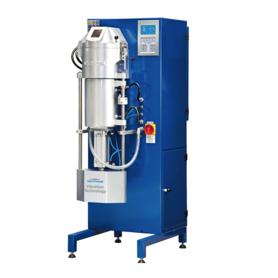
System description Schematic representation Figure 1: overall view pos. designation Function bell with window Closing the inductor housing. inductor housing (cruci- In the inductor housing are: ble chamber) Induction coil crucible insulation vacuum chamber With water cooling inlet and outlet. flask lift Enables lifting of tank. -
Page 20: Backside Connections
Storage area for manual. Back door Service access (only for experts for open with tool) Serial Interface/RS232 Connection for PC over Indutherm-RS232-cable (socket actual attached to internal modem). Power supply Power supply of the vacuum pressure casting machine. Vacuum pump Socket for plug from vacuum pump. -
Page 21: Setup Of The Crucible Chamber
System description Setup of the crucible chamber Figure 4: Setup of the crucible chamber position designation Function metal filter C038 Brass filter for cleaning atmosphere in inductor chamber. thermocouple socket Thermocouple connector for wall measurement if you work (option) with centre measurement additional (option). filling cone Top insulation and help for filling crucible. -
Page 22: Special Options
System description Special options 4.5.1 Centre-and wall measurement (Dual measurement) Figure 5: option – dual measurement With a software level higher than 8000.0082, the slave temperature is displayed in brackets from a value above 100 °C. °C (0550) 1000°C 0.00 Test crucible Program... -
Page 23: Granulation Tank
System description 4.5.2 ranulation tank Figure 6: granulation tank position designation function protective gas entry Here you can supply additional protective gas. water outlet Usual water outlet. O-Ring For sealing of the barrel without a gap. Inside barrel with lever Removable inside barrel with fast emptying function. fresh water input Control the fresh water input. -
Page 24: Transport
Transport Transport Danger! Lethal injuries with wrong transport by fork lift truck. Take care of the right position using transport device to avoid tilting of the system. Pick up the system only from the side, because centre of gravity is in the upper front third. If the fork is too small or too narrow adjusted there is a danger of system tip over from the mean of transportation. -
Page 25: Mountingandcommissioning
Mounting and commissioning Mounting and commissioning Safety advices for mounting Danger! Only experts may work at the electrical equipment. Danger! Observe the mains supply to requirements of the local electricity supply company, the VDE and the local electricity company. Close the system always via the 5-pin power plug to the power sup- ply. -
Page 26: Apply Supply Connections
Mounting and commissioning Apply supply connections 6.3.1 Power supply The electrical connection may only be performed by a specialist. Note the information specified on the nameplate rated voltage or frequen- The 3-phase power supply may differ max. +/- 10% from the rated voltage. -
Page 27: Vacuum
Mounting and commissioning Figure 8: constant pressure regulator 2x gauges in bar/PSI/kPa/MPa. Never in liter/minute (l/min)!!!! 6.3.5 Vacuum Here, a vacuum pump with a suction capacity of at least 21 m³ / h and a final pressure of 2 mbar should be connected. The connection must be via a special vacuum tube with a cross section inside of 13 mm carried out (article no. -
Page 28: Rs232
Here, the machine can be connected to a PC. Use the data manage- ment software provides by Indutherm to read system data and casting programs. It can also record casting logs electronically. Figure 9: data management software menu sales@romanoff.com | romanoff.com... -
Page 29: Operation
Operation Operation Safety advices for operation Caution! Examine all consumables, insulations and hoses before switching on. Check for damages and cleanliness, especially crucible and insulations. Operate the system only when it’s free of damages. Warning! Risk of burning on hot surfaces and hot metal (until ~ 1500 °C). -
Page 30: Changing Casting Parts
Operation Attention! At crucible temperatures over 100 °C the cooling water supply must be switched on. If it is not turned on, the inductor will be destroyed. If cooling water supply fails, the heating system immediately is turned off. Inspect the system for damage before putting back into operation again. -
Page 31: Front Panel
Operation Front panel 7.3.1 LCD screen after mains switch on Figure 11: main screen upper area = Actual state of °C machine 0010°C 0.00 InduTest Crucible Program 0.00 Flask Manual lower area = Temp. Temp. Program Program Program options – –... -
Page 32: Program Change
Operation 7.3.2 Program change page 1 Figure 12: Program 0028 Program InduTest parameter page 1 0010°C Temperature 0000 Washingwhile heating At Start Insert Flask/Ingot upper area = Pa- -1.0bar Melting pressure rameter 0010s Melting time Flask Castingmould Manual Castingmode 0000 s Pre cast vacuum 02.0 s Castingpressurestart... - Page 33 Operation 0000 s Pre cast ‘0’ to ‘20’ s Set value for a quick evacuation time step in the vacuum crucible chamber right before initiation of the pour- ing step; this removes gas from the interior of the mould/flask but avoids extended melting time under vacuum.
- Page 34 Operation 7.3.3 Program change page 2 Figure 13: Program 0028 Program InduTest parameter page2 -1.0bar Flask pressure 0020 Vibration 0020 Cooling time upper area= pa- 0000s Cooling time pressureless rameter Automat. Openingmode vacuumchamber Automat. Alloy mixing Label [InduTest… ] lower area = Main Λ...
-
Page 35: Predefined Casting Programs
Operation 7.3.4 Predefined casting programs Figure 14: pre-setcasting programs VC480V Material Bronze Yellow Yellow Alumini- Brass gold gold 14 kt 18 kt (with zinc) Crucible Graphite Graphite Graphite Graphite Graphite Program no. Temperature °C 1150 1060 1080 1080 Washing while heating 0001 0001 0001... -
Page 36: System Parameter
Operation System parameter If you start from the main page and you press ‘Program Setup’ for five seconds you get access to the system parameter level. Figure 15: System parameter Display-functions: 000: 00002 Selected parameter: 000 Value of parameter is 2, which means here thermocouple type N is activated. -
Page 37: State Level
Operation 7.4.1 State Level By pressing the ‘Service’-button once, you see the software ID, generator number and machine number. Figure 16: Service-Info-Page1 Service Info Page1 800.0096 SW- ID.Build (Mar 10201615:14:42) F0936Generator No. (SER ETHUSB) M15297Machine No. Service Service Print Pressing ‘Service’ second time display switches to the second service info page amongst other with important information on the cooling water flow, generator temperature, ma- chine state and signal strength of inbuilt modem. -
Page 38: Vc480V Front Panel Below Display
Operation VC480V Front panel below display Figure 18: Front panel below display Manual control: Generator By this button you can start heating from generator. Switched on genera- Start tor regulate for the set temperature (see above ‘temperature’). Generator Stops heating (if not operating in program). Stop Vacuum Opens the vacuum chamber. -
Page 39: Protective Gas Flow
Operation Protective Gas flow Protective gas supply for pressure regulation in the crucible occurs automatically. For safety reasons: there is continuous flow of protective gas at temperatures over 500 °C, because there is danger of blow up. Casting Before starting check chambers, crucible and crucible shield for dirt, residues or possible damage. - Page 40 Vibration starts 1 second after opening of sealing rod in the automatic program mode, if there is a vibration time bigger then 0 programmed. Note: At our webpage www.INDUTHERM.de youʼll find a train- ing video of VC450 and VC650V. This should give you an idea how to use your VC480V.
- Page 41 Wait for the automatic opening of the vacuum chamber. Swivel out vacuum chamber and take out flask. A new casting cycle can start, beginning with step 3! Recommendation INDUTHERM: Before you do your first castings with your material let run the test program at room temperature with cold flask.
-
Page 42: Possible Causes For Dissatisfying Casting Results
13. Contamination in the investment because of wax residues (steam out flasks). 14. Graphite contamination (use ceramic insert or crucible of better graphite quality). Please note that INDUTHERM cannot be held responsible for dissatisfying casting re- sults. sales@romanoff.com | romanoff.com... -
Page 43: Flask Structure
Operation Flask structure Figure 19: sectional view of flask Figure 20: flask without flange and holes Note: The principle of the machine is based on the high gas flow through the machine. Please use only flasks with holes on the side. ☑... -
Page 44: Granulating
Operation 7.10 Granulating Before starting check crucible, sealing rod and crucible insulation for dirt residues/possible damages. It is recommended to use a vacuum cleaner for the entire inductor. The metal filter (left of the sealing rod) should be taken out and cleaned with compressed air. Use a dustproof mask and blow not in the room! A crucible with a hole of a 2-mm-diameter is recommended. - Page 45 Operation Suggestion for a granulating process: 1. Switch on cooling water, compressed air and protective gas supply. 2. Fill the granulating tank with water until overflow. 3. Switch on VC480V at the mains switch. Figure 23: adapter for flask chamber 4.
-
Page 46: Error Diagnosis
Operation Figure 24: granulating insert Take out insert. Pour out the water. Take out material. 7.11 Error diagnosis There two types of disturbances. Error and warnings. If there is an error, the heating will be stopped and there is shown an error code in display. -
Page 47: Diagram Casting Flasks Without Flange
7.15 Service If you need technical support from company INDUTHERM, we’d like to have followinginformationof your machine at first contact: Service No. M17999 F below mains switch or Serial number M17999 from identification plate at machine back- side. -
Page 48: Maintenance
Maintenance Maintenance Safety advices for repair and maintenance For reliable use and highest work accuracy use is regular mainte- nance and service of your system a prerequisite. The necessary working steps are summarized in this chapter and have to carry out in time. - Page 49 Maintenance Warning! Risk of injury. Make pressurized plant parts at zero pressure before work is carried out there. Warning! Slipping on the floor in the area around the plant, if lubricants or sol- vents were spilled. Clean the floor with dirt immediately! Discard the cleaning cloths in the collecting means made available.
-
Page 50: Maintenance Schedule
Maintenance Maintenance schedule Follow the maintenance schedule to obtain the functionality of the system. Daily (before casting) Warning! Burning hazard because of leaking molten metal. The system must not be operated without a sealing rod for security reasons. The tip of the sealing rod must stay in the pouring opening even when sealing rod is open. - Page 51 Maintenance Figure 28: air filter of vacuum pump Every year If you use tap water for cooling water-system, then pump about 25% citric acid solution for about an hour through the system. Af- terwards the system should be thoroughly flushed with clean wa- ter and checked for possible leaks.
-
Page 52: Repair
Maintenance Repair The system must be repaired only by authorized personnel. Never try to repair the system yourself. Incorrect repairs can lead to health problems or damage to the equipment. *Directive 2009/104/EG of the European Parliament and of the Council of 16 September 2009 concerning mini- mum safety and health protection for the use of work equipment by workers at work (sec- ond individual Directive within the meaning of Article 16 paragraph 1 of Directive 89/391 / EEC). -
Page 53: Dismantlingandcleaningup
Dismantling and cleaning up Dismantling and cleaning up Warning! Permanent skin damages after touching lubricant or sol- vent of every description (long term effects). Avoid touching lubricants, solvents and coolants. Wash the sprinkled skin parts thoroughly. Wear protective gauntlets when using lubricants, solvents and coolants. -
Page 54: Annexe
Annexe Annexe 10.1 List of figures Figure 1: overall view ..............4–2 Figure 2: backside of the vacuum pressure casting machine ..4–3 Figure 3: details of connections ............4–3 Figure 4: Setup of the crucible chamber .........4–4 Figure 5: option – dual measurement ..........4–5 Figure 6: granulation tank ..............4–6 Figure 7: lifting the weight ..............5–1 Figure 8: constant pressure regulator ..........6–3... -
Page 55: Ce-Declaration Of Conformity
Annexe 10.2 CE-Declaration of conformity Manufacturer: INDUTHERM Erwärmungsanlagen GmbH Brettener Str. 32, 75045 Walzbachtal Product type: Vacuum-pressure-casting-machine Machine type: VC400, VC450(V), VC480(V) Serial number: 10081 or higher Authorized to sign: Peter Hofmann We herewith declare that the machine named above corresponds to the essential safety and health requirements of the following EC directives because of its design and construction in the version which we have placed on the market. - Page 56 The declaration of conformity relates only to the machine in the state in which it was placed on the market; Parts and / or retrospective interventions carried out subsequently by the end user remain unaffected. The test protocols are stored at INDUTHERM Erwärmungsanlagen GmbH for 10 years. city/date/signatory:Walzbachtal/2017-10-16/PeterHofmann, chairman sales@romanoff.com | romanoff.com...
-
Page 57: Test Result Chart
Annexe 10.3 Test result chart sales@romanoff.com | romanoff.com 10–4... -
Page 58: Connection Diagrams
Annexe 10.4 Connection diagrams 10.4.1 Connection diagram machine with 3x 400V Figure 30: connection diagram – power part 3x400V sales@romanoff.com | romanoff.com 10–5... - Page 59 Annexe Figure 31: connection diagram – control sales@romanoff.com | romanoff.com 10–6...
- Page 60 Annexe Figure 32: connection diagram – temperature sensor, digital I/O sales@romanoff.com | romanoff.com 10–7...
-
Page 61: Connection Diagram Machine With 3X 230V
Annexe 10.4.2 Connection diagram machine with 3x 230V Figure 33: connection diagram – power part 3x230V sales@romanoff.com | romanoff.com 10–8... -
Page 62: Water Cooling Circuit
Annexe 10.5 Water cooling circuit Figure 34: water cooling circuit sales@romanoff.com | romanoff.com 10–9... -
Page 63: Assembly Drawing Vc480V
Annexe 10.6 Assembly drawing VC480V Figure 35: Assembly drawing with wall measurement Assembly drawing VC400, VC450, VC450V, VC480V, VC500 vacuum casting with wall measurement C081 Attention: The numbers like C008are placeholder for the posi- tion in the machine. The article number to order this piece is 8 digits and listed in your machine specific order list G17999_00.pdf. -
Page 64: Consumable And Spare Parts List
Annexe 10.7 Consumable and spare parts list INDUTHERM is now using only machine specific spare parts list, which contain all the information for your machine. At following page, the spare parts list for this machine will start. The item number of the consumables list is composed by following parts: G (for starter kit/basic equipment) The next five digits are the machine service number. - Page 65 Annexe Replace this sheet with G17999_00 sales@romanoff.com | romanoff.com 10-12...
-
Page 66: Error And Warning Messages
Error and warning messages Software-Documentation starts at next pages. The label of the bilingual documentation is “generator_documentation_80000xxx_customer_DM_F_PM_Gen.pdf”. Please note: At our Internetpage http://www.indutherm.de/webshop you can get prac- tical help for troubleshooting. Figure 36: contact form webshop Until you can enjoy the ad- vantages of the Webshop you have to apply for an access.
Need help?
Do you have a question about the ROMANOFF VC480V and is the answer not in the manual?
Questions and answers