Table of Contents
Advertisement
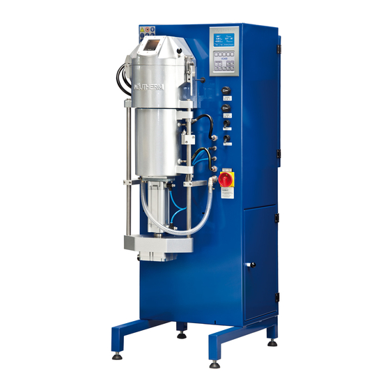
Instruction Manual for
Vacuum Pressure Casting Machine
VC 400 LCD
machine-service-no.
Indutherm order service
Indutherm
for consumables:
technical service
M16999 F
+49 7203 9218-40
+49 7203 9218-41
Tel.:
Tel.:
sales@indutherm.de
support@indutherm.de
INDUTHERM Erwärmungsanlagen GmbH
Tel.: +49 (0)7203 9218-0
Brettener Straße 32
Fax: +49 (0)7203 9218-70
D-75045 Walzbachtal
e-mail: info@INDUTHERM.de
Germany
Advertisement
Table of Contents

Subscribe to Our Youtube Channel
Related Manuals for Indutherm VC 400 LCD


Summary of Contents for Indutherm VC 400 LCD
- Page 1 Instruction Manual for Vacuum Pressure Casting Machine VC 400 LCD machine-service-no. Indutherm order service Indutherm for consumables: technical service M16999 F +49 7203 9218-40 +49 7203 9218-41 Tel.: Tel.: sales@indutherm.de support@indutherm.de INDUTHERM Erwärmungsanlagen GmbH Tel.: +49 (0)7203 9218-0 Brettener Straße 32...
-
Page 2: Table Of Contents
Contents Contents .......................... 2 Introduction ......................3 General description of the VC400 ............... 3 Machine components ..................3 Technical data ..................... 4 General information ..................... 5 Putting into operation ....................7 Set-up directions ....................7 Mains supply ......................7 Cooling water ....................... 7 Protective gas (Argon or Nitrogen) .............. -
Page 3: Introduction
The machine consists of separate units built into one casing: Inside the casing, the following components are installed: microprocessor controlled induction generator F-type with serial number F and 4 digits (Important for INDUTHERM!), medium frequency transformer, oscillation circuit capacities, pneumatic valves, pressure control for sealing pressure of sealing rod cylinder and pressure control for protection gas. -
Page 4: Technical Data
170 cm max. Ø 130 mm (5“) * 260 mm (10“) height Flask Crucible temperature max. 1400 °C with type S thermocouple Generator INDUTHERM F type Melting performance 3.5 kW 4.5 kW Mains supply 1x230V/1x16A, 50 or 60 Hz 3x400V/3x16A, 50 or 60 Hz Cooling water supply 2.5 - 5 bar/at least 200 l/h... -
Page 5: General Information
1.4 General information Safety information In order to ensure a constant, ideal performance of the machine and to ensure safe working conditions, the user is to observe the following safety measures: The complete electrical wiring is to be performed only by qualified and specially trained personnel. - Page 6 This machine was designed for use in closed spaces (indoors) and may only be used for the above-mentioned purpose. Only original INDUTHERM consumable and spare parts are to be used. The machine may not be modified in any way. Technical changes may only be effected with INDUTHERM GmbH’s prior written permission.
-
Page 7: Putting Into Operation
2 Putting into operation On delivery, immediately check if the machine is complete and if there are any transportation damages. In the case of damages, please contact at once supplier or forwarding agent. 2.1 Set-up directions The machine should be placed on clean and dry ground. The ground should be even, solid and level. -
Page 8: Protective Gas (Argon Or Nitrogen)
2.4 Protective gas (Argon or Nitrogen) Purity to be no less than 99.95% must be used as protective gas. Use a compressed air hose with an inner ø of 6 mm. The inlet pressure must be 8 bars. The machine will start adding protective gas into the inductor housing at temperature higher the 500 °C. -
Page 9: Safety
The machine has been developed for use in enclosed spaces and for the above mentioned application. Only original INDUTHERM consumables and spare parts are admitted for operation. It is not allowed to change or vary the system in any way. Technical changes need explicit written approval of INDUTHERM. -
Page 10: Demands On Staff, Duty For Utmost Care
3.2 Demands on staff, duty for utmost care Work on and with the machine is allowed to be accomplished by reliable, trained and instructed staff only. Responsibilities for the separate sections have to be regulated clearly which include operation, preparation, service and repair. Only authorized personnel may act at the system. - Page 11 3.3.1 Concept of safety Objective is the safety of the staff against injuries of the system against damage or standstill of the environment against endangering The list of actions taken: deployment of protective equipment like covers and main-switch with emergency stop function, ...
- Page 12 3.3.4 Main switch with emergency stop function It is allowed to start the machine or operation only with proper emergency stop function. Caution! With the emergency stop function you can stop the machine in critical moments of health hazard. You help to diminish potential consequences of injury.
-
Page 13: Safety Marking
3.4 Safety marking The following signal words are used in this document which are associated with safety markings for presentation of possible dangerous situations. Danger! Death, serious body injury or substantial property damage will result if proper precautions are not taken. Warning! Death, serious injury or substantial property damage can result, if proper precautions are not taken. -
Page 14: Safety Advices
3.5 Safety advices Check always the condition of the system before you switch on the system. Examine the supply pipes and insulations if there are leaks and damages. Operate the system only if it is in proper and faultless shape. Operate the system never: ... - Page 15 Danger! Danger for the eyes. Always place the gold coated foil for eye protection against thermal radiation on top of the inspection window of the crucible chamber. In addition wear safety goggles suitable for welding operations Danger! Danger because of touching parts conducting voltage.
- Page 16 Danger! At crucible temperatures over 100 °C the cooling water supply must be switched on. If it is not turned on, the inductor will be destroyed. If cooling water supply fails, the heating system immediately is turned off. Inspect the system for damage before putting back into operation again.
-
Page 17: Residual Risks
Caution! Observe regulations for the mains supply written from the responsible electric power supply company, the association VDE and the local electric power station. Inappropriate connecting can lead to injuries and damages of the machine. 3.6 Residual risks risk characterisation risk reduction Health risk for persons with Instruct people. -
Page 18: Operation
4 Operation 4.1 Operating elements 4.1.1 VC400 screen when starting the machine Top level = Actual program status Bottom level = Selectors for different values On the top level shown: 378 °C == actual temperature 1000 °C == set temperature ‘1.46 bar crucible == actual crucible pressure (-1 to 1.5 bars) ‘-1.00 bar flask... - Page 19 4.1.2 VC400 modify program screen Top level = Actual program status Bottom level = Selectors for different values On the top level shown: 0001 program == selected program to modify 1000 °C temperature == set temperature inside the crucible 0100 % heating power == heating power from 5-100% == time between confirming the “manual cast”...
- Page 20 4.1.3 Pre-set casting programs VC400 / VC500 Aluminium Brass Material Bronze Yellow Yellow Silver Test gold 14k gold 18k (with zinc) Crucible Graphite Graphite Graphite Graphite Graphite Graphite Graphite Program No. Temperature °C 1150 1060 1080 1080 1000 0010 Heating 0100 0100 0100...
- Page 21 4.1.5 VC400 service info page 1 If you press now „Service“-button you see the software ID, generator number and machine number. If you press service again you get to the next page. 4.1.6 VC400 service info page 2 Here you see the water flow, the generator temperature and other features. page 21 86014010_04_OPERATING_MANUAL_VC400_LCD_GB.DOC 25.11.2016 KS...
- Page 22 4.1.7 VC400 buttons below display Generator area: Generator Stop == stops heating ( if not operating in program ) Generator Starts == starts heating Generator + == increases output power of generator Generator - == decreases output power of generator PGM Start == downloads the program settings into memory and starts program...
-
Page 23: Casting
Flask (rotary switch): By using this rotary switch, select if the flask is to be evacuated or ventilated. Locked- Standard position to add or remove the flask into the vacuum chamber. Vacuum- After putting in place the flask, the vacuum is turned on. - Page 24 Switch on vacuum casting machine and vacuum pump. Grind in the sealing rod into the crucible bottom (rotating movement) Set the desired melting program. Select 'normal’ with the valve ‘crucible’ (standard selection: normal-pressure). If pressure or vacuum is selected, the vacuum chamber must be closed with your flask already inside.
- Page 25 Release the vacuum with the valve ‘flask’. If the crucible was put under over- or under-pressure, also release it with the valve ‘crucible’ to ‘normal’ position. Lower the vacuum chamber with the valve ‘chamber lift’ and swing out the chamber. Now the flask can be removed.
-
Page 26: Possible Causes For Dissatisfying Casting Results
12. Vacuum was turned on too late/turned off too early. 13. Contamination in the investment because of wax residues (steam out flasks). 14. Graphite contamination (use ceramic insert or crucible of better graphite quality). Please note that INDUTHERM cannot be held responsible for dissatisfying casting results. page 26... -
Page 27: Configuration Of Flask
4.4 Configuration of flask page 27 86014010_04_OPERATING_MANUAL_VC400_LCD_GB.DOC 25.11.2016 KS... -
Page 28: Granulating
4.5 Granulating Before starting check crucible, sealing rod and crucible insulation for dirt residues/possible damages. It is recommended to use a vacuum cleaner to clean the entire inductor. The metal filter (left of the sealing rod) should be taken out and cleaned with compressed air. -
Page 29: Consumable Parts
5 Consumable parts 5.1 Assembly drawing VC400 Attention: The numbers like C008 are placeholder for the position in the machine. The article number to order this piece is 8 digits and listed in your machine specific order list G16999_00.pdf. -
Page 30: Consumables And Spare Parts List
5.2 Consumables and spare parts list At following side the spare parts list for this machine will start. INDUTHERM is now using only machine specific spare parts lists, which contain all the information for your machine. The name is encoded. One example could be G15033_VC_68_169_00... - Page 31 Telephone no +49-7203-9218-40. Attention! Please understand that INDUTHERM has to support more than 3000 machines. We cannot sort spare parts only with your customer name. We always need your machine service number, to send you the correct spare part.
- Page 32 This page will be replaced with G16999_00 (16999= machine no.). _00 is version of spare parts list. Changes will be done with _01, _02, due to customer’s requirements. Example: G16999_01 (second version of the list for machine 16999). page 32 86014010_04_OPERATING_MANUAL_VC400_LCD_GB.DOC 25.11.2016 KS...
-
Page 33: Service
6 Service 6.1 Troubleshooting Only trained personnel should open the machine. The machine cannot be turned on: - when there is no mains supply. The heating cannot be turned on: - when there is no cooling water supply, - when there is no compressed air supply, - when there is no protective gas supply, - when thermocouple is not in place or defective and - when generator is running hot. -
Page 34: Diagram Casting Flasks Without Flange
6.2 Diagram casting flasks without flange Possible problems of losing vacuum 1.) O-Ring vacuum chamber is not OK. force of the overpressure 2.) Flask top surface is not flat vacuum area enough. 3.) Silicon ring is missing or defect. 4.) Flask lift cylinder is not in “up” position. -
Page 35: Maintenance
6.4 Maintenance A routine check/regular cleaning of the following is necessary: (Caution: disconnect the machine first!): Daily (before casting): 1. Remove thermocouple, sealing rod, crucible and insulation materials, carefully clean inductor housing with a vacuum cleaner. Before reinstalling the above parts, check those and replace if necessary. -
Page 36: Declaration Of Conformity
6.5 Declaration of conformity page 36 86014010_04_OPERATING_MANUAL_VC400_LCD_GB.DOC 25.11.2016 KS... - Page 37 page 37 86014010_04_OPERATING_MANUAL_VC400_LCD_GB.DOC 25.11.2016 KS...
-
Page 38: Connection Diagrams
7 Connection diagrams page 38 86014010_04_OPERATING_MANUAL_VC400_LCD_GB.DOC 25.11.2016 KS... - Page 39 page 39 86014010_04_OPERATING_MANUAL_VC400_LCD_GB.DOC 25.11.2016 KS...
- Page 40 page 40 86014010_04_OPERATING_MANUAL_VC400_LCD_GB.DOC 25.11.2016 KS...
-
Page 41: Test Result Chart
8 Test result chart... -
Page 42: Software Documentation
9 Software documentation The software documentation INDUTHERM article no. 86380000 with the error and warning codes start on the next pages. For the F generator the software starts with 80000 xx = software index. Attention: On our new Internet page http://www.indutherm.de/webshop...
Need help?
Do you have a question about the VC 400 LCD and is the answer not in the manual?
Questions and answers
Como resolver o erro 014
@Israel Alves Moreira A maquina nao esta ligando