Table of Contents
Advertisement
Brettener Strasse 32
D-75045 Walzbachtal
Germany
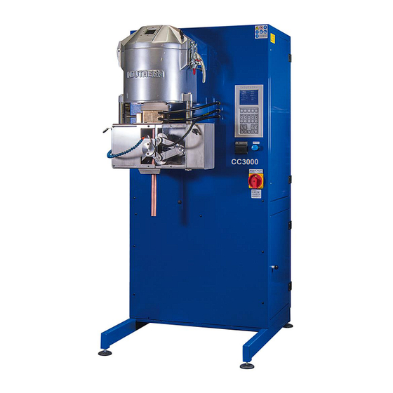
CC3000
VCC1000
Both pictures with options!
Technical Documentation
Continuous-Casting-Machine (V)CC1000 /
(V)CC3000 with PM-generator
Machine-service-no.
Indutherm order service
Indutherm
for consumables:
technical service
M17999 PM
+49 7203 9218-40
+49 7203 9218-41
Tel.:
Tel.:
sales@indutherm.de
support@indutherm.de
Keep for future use!
t
Advertisement
Table of Contents


Need help?
Do you have a question about the CC3000 and is the answer not in the manual?
Questions and answers