Table of Contents
Advertisement
Quick Links
Advertisement
Table of Contents

Related Manuals for Hypertherm Abrasive Regulator II


Summary of Contents for Hypertherm Abrasive Regulator II
- Page 1 Abrasive Regulator II ™ Instruction Manual 809030 | Revision 0 | English...
- Page 2 Europe, Middle East, and Africa USA and Canada Technical service Technical service 00 800 4973 7843 Toll-free 800-643-9878 Toll-free +31(0) 165 596900 TechnicalService-Hanover@Hypertherm.com +31(0) 165 596906 Fax Customer service TechnicalService-HyperthermEurope@Hypertherm.com 800-737-2978 Toll-free Customer service Return materials 00 800 3324 9737 Toll-free...
- Page 3 Abrasive Regulator II Instruction Manual 809030 Revision 0 English Original Instructions October 2015 Hypertherm Inc. Hanover, NH 03755 USA www.hypertherm.com...
-
Page 5: Table Of Contents
Contents Warranty ........................... SC-7 Environmental stewardship ....................SC-9 Proper disposal of Hypertherm products ........................... SC-9 Particle emission and wastewater quality .......................... SC-9 Safety ............................SC-11 National and local safety regulations ..........................SC-11 User qualification and training ............................SC-11 Symbols and marks ......................SC-13 1 Terminology .......................... - Page 6 Contents Abrasive Regulator II Instruction Manual 809030...
-
Page 7: Warranty
600 hours of use with the use of a thimble filter Diamond orifices and compliance with Hypertherm’s water quality requirements Consumable parts are not covered by this warranty. Consumable parts include, but are not limited to, high-pressure water seals, check valves, cylinders, bleed-down valves, low-pressure seals, high-pressure tubing, and low- and high-pressure water filters. - Page 8 Warranty SC-8 Safety and compliance...
-
Page 9: Environmental Stewardship
Hypertherm waterjet cutting systems, like all products with electronics, can contain materials or parts, such as printed circuit boards, that can not be discarded with ordinary waste. It is your responsibility to dispose of Hypertherm product or part in an environmentally suitable manner and in compliance with national and local codes. - Page 10 Environmental stewardship SC-10 Safety and compliance...
-
Page 11: Safety
The end user is responsible for the safe operation of this equipment. The safety precautions in this manual are general and can not anticipate every situation. Hypertherm Inc. acknowledges that unforeseen situations due to equipment failure, site variability, insufficient maintenance, failure of control equipment, and other events can cause equipment damage, injuries, or death. - Page 12 Safety SC-12 Safety and compliance...
-
Page 13: Symbols And Marks
Symbols and marks Information and hazard symbols Some symbols in this table could be relevant to other products. This symbol identifies an imminently hazardous situation, which, if not avoided, will result in death or serious injury. DANGER This symbol identifies a potentially hazardous situation, which, if not avoided, could result in death or serious injury. - Page 14 Symbols and marks SC-14 Safety and compliance...
-
Page 15: Terminology
A flexible hollow cylinder; dimensions are based on its inside diameter (ID) inside diameter The diameter measurement of the inside of a cylinder The International Organization for Standardization is an independent membership organization that develops voluntary standards Abrasive Regulator II Instruction Manual 809030... - Page 16 Water that is not pressurized by the intensifier National pipe thread taper, a common United States standard for tapered threads that are used on fittings and pipes An original equipment manufacturer of machines that include Hypertherm products that are sold directly to end users outside diameter The diameter measurement of the outside of a cylinder Pound-force per square inch is a unit of pressure;...
-
Page 17: Product Description
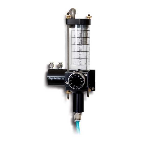
The control knob changes the flow rate of abrasive to the cutting head. The control knob is marked from 1 to 10. The flow rate is adjustable during cutting. Abrasive Regulator II Instruction Manual 809030... - Page 18 Product description Abrasive Regulator II Instruction Manual 809030...
-
Page 19: Operation
Close the regulator When air enters the cylinder's inner connection the gate closes and the abrasive stops flowing. The air leaves the regulator through the outer connection to a vent. Abrasive Regulator II Instruction Manual 809030... - Page 20 1.92 0.58 This chart is based on 80-mesh alluvial abrasive. Flow rates can vary due to grit size. Suggested setpoints Orifice/nozzle .010/.030 .011/.030 .012/.030 .014/.040 .016/.040 Control knob setting 5-1/3 5-2/3 7-1/3 7-2/3 Abrasive Regulator II Instruction Manual 809030...
-
Page 21: Adjust The Regulator For A New Abrasive
25.6 38.4 1089 9. Turn the control knob clockwise to increase the flow rate. Turn the control knob anticlockwise to decrease the flow rate. 10. Repeat this procedure until the flow rate is acceptable. Abrasive Regulator II Instruction Manual 809030... - Page 22 Operation Use this table to record calibration details for other abrasives. Pounds per Grams per minute Control knob Abrasive material minute (lb/min) (g/min) setting Abrasive Regulator II Instruction Manual 809030...
-
Page 23: Preventive Maintenance
Section 4 Preventive maintenance Hypertherm products are designed and manufactured with a commitment to continuous quality control and safety. Contact a Hypertherm Technical Service Associate or an OEM for information about the installation, operation, maintenance, and repair of this equipment. -
Page 24: Safety
Keep parts available so that they are ready when required. Follow local protocols for recycling or disposal of parts and materials. Refer to Recycling and end of product life on page 42. Abrasive Regulator II Instruction Manual 809030... -
Page 25: Replace Worn Plates
Alignment tool such as a dowel Disassemble the regulator 1. Remove the thumb nuts from the bottoms of the threaded rods. 2. Remove the regulator base. 3. Remove the 2 socket-head cap screws from the control knob mounting plate. Abrasive Regulator II Instruction Manual 809030... - Page 26 7. Remove the 4 socket-head cap screws from the air cylinder. 8. Remove the aperture plate, the sandwich plate, and the exit plate. The gate stays in place. 1 Gate 3 Aperture plate 2 Sandwich plate 4 Exit plate Abrasive Regulator II Instruction Manual 809030...
- Page 27 Put the face with THIS SIDE UP toward the housing base. Put the end with THIS END TOWARDS KNOB toward the knob on the housing base. 2. Put the aperture plate between the exit plate and the gate. Gate Aperture plate Abrasive Regulator II Instruction Manual 809030...
- Page 28 5. Install the washers, springs, and shoulder bolts in the aperture assembly holes. Tighten the bolts. Put the washer in with the flat side down. 6. Install the socket-head cap screws in the air cylinder body. Tighten the screws. Abrasive Regulator II Instruction Manual 809030...
- Page 29 11. Put the regulator base on the threaded rods. 12. Reassemble the thumb nuts on the threaded rods. Hand tighten the thumb nuts with the knurled side toward the end of the threaded rod. Abrasive Regulator II Instruction Manual 809030...
-
Page 30: Recalibrate The Control Knob
1 Metering aperture 2 Gauge pin 3. Remove the dial label from the control knob. 4. Put a new dial label on the control knob so that the pointer lines up with the 1. Abrasive Regulator II Instruction Manual 809030... -
Page 31: Parts Lists
Genuine Hypertherm parts are the factory-recommended replacement parts for this pump. The Hypertherm warranty might not cover damage caused by using nongenuine Hypertherm parts. To order parts, contact the original equipment manufacturer (OEM) or Hypertherm Inc. with the part numbers and quantities. -
Page 32: Replacement Parts
1/8-inch NPT × 1/4-inch air tube fitting 13615 3/8-inch OD × 1/4-inch ID polyurethane delivery tube (9.53 mm OD × 6.35 mm ID tube) 11485 Dial label Other parts 13727 Coned rubber splash guard Abrasive Regulator II Instruction Manual 809030... -
Page 33: Complete List Of Preventive Maintenance Parts, Tools, And Materials
1/8-inch hex wrench 5/32-inch hex wrench 3/16-inch hex wrench (or 5 mm wrench) Compressed air source 0.038-inch diameter gauge pin Alignment tool such as a dowel (recommended) Materials Scale Stopwatch Container for measuring abrasive Abrasive Regulator II Instruction Manual 809030... - Page 34 Parts lists Abrasive Regulator II Instruction Manual 809030...
-
Page 35: Troubleshooting
If the abrasive does not flow, check for moisture in the abrasive or too much air in the feed hose. Moisture in the abrasive Prevent humidity in the abrasive with an air dryer on the supply air. 1 Vent hole 3 Delivery tube 2 Regulator base Abrasive Regulator II Instruction Manual 809030... - Page 36 7. Wipe out the acrylic tube with a lint-free towel or blow it dry with compressed air. Do not use soap, detergent, or solvents. 8. Reassemble the regulator. 9. Reconnect the delivery tube to the cutting head. Abrasive Regulator II Instruction Manual 809030...
-
Page 37: Installation
Refer to the instruction manual. Read and understand all of the safety guidelines in this manual. Keep the work area clean and free of fluid spills. Hypertherm products are designed and manufactured with a commitment to continuous quality control and safety. Contact a Hypertherm Technical Service Associate for information and support regarding the installation, operation, maintenance, and repair of this equipment. -
Page 38: Requirements
3/16-inch hex wrench (5 mm wrench) Two 1/4-20 socket head cap screws (M6 socket head cap screws) 13615 3/8-inch OD × 1/4-inch ID polyurethane delivery tube (9.53 mm OD × 6.35 mm ID tube) Abrasive Regulator II Instruction Manual 809030... - Page 39 7. If the thumb nuts and threaded rods were moved, adjust the threaded rod so that about 2.5 cm (1 inch) of rod shows on each end. Hand tighten the thumb nuts with the knurled part toward the end of the threaded rod. 8. Connect the polyurethane delivery tube to the delivery tube fitting. Abrasive Regulator II Instruction Manual 809030...
-
Page 40: Connect The Abrasive Regulator To The Solenoid Valve
The diagram shows a 2-position 4-way solenoid valve in the typical position. Refer to the solenoid valve manufacturer’s instructions to connect the solenoid valve to the abrasive regulator. 3. Make sure that the abrasive regulator operates properly. Abrasive Regulator II Instruction Manual 809030... -
Page 41: Connect The Abrasive Regulator To The Abrasive Pot
For longer delivery lengths, increase the pot pressure. Refer to the abrasive pot manufacturer’s instructions to adjust the pot pressure. 5. Disconnect the delivery tube from the regulator base. 6. Open and close the abrasive regulator to make sure that abrasive comes out. Abrasive Regulator II Instruction Manual 809030... -
Page 42: Recycling And End Of Product Life
At the end of the life of the product or its parts, recycle or dispose of relevant materials and parts using an environmentally satisfactory method and in accordance with local regulations. If the product contains substances that are harmful to the environment, remove and dispose of them in accordance with current local regulations. Abrasive Regulator II Instruction Manual 809030... - Page 43 HyPrecision and Hypertherm are trademarks of Hypertherm Inc. and may be registered in the United States and other countries. All other trademarks are the property of their respective holders. © 2015 Hypertherm Inc.
Need help?
Do you have a question about the Abrasive Regulator II and is the answer not in the manual?
Questions and answers