
Subscribe to Our Youtube Channel
Related Manuals for Powell PowlVac 63kA


Summary of Contents for Powell PowlVac 63kA
- Page 1 IB-26100 PowlVac 63kA Enclosed Indoor ® Disconnect Switch Model: 15.0kV, 63kA 5000A August, 2005 Powered by Safety ®...
- Page 2 Enclosed Indoor Disconnect Switch IB-26100 Contact Information Powell Electrical Systems, Inc. www.powellind.com Powell Apparatus Service E-mail: Info@powellservice.com PO Box 12818, Houston, Texas 77217-2818 Tel: 713-944-6900 Fax: 713-947-4453 Powered by Safety ®...
-
Page 3: Table Of Contents
Enclosed Indoor Disconnect Switch IB-26100 Contents INTRODUCTION ..........................2 A. SCOPE ...........................2 B. PURPOSE ..........................2 C. INSTRUCTION BULLETINS AVAILABLE ON THE INTERNET ..........2 SAFETY ............................3 A. SAFE WORK CONDITION .....................3 B. SAFETY RULES ........................3 General ..........................3 C. SAFETY LABELS ........................4 III. DESCRIPTION ..........................5 A. - Page 4 Enclosed Indoor Disconnect Switch IB-26100 Figures ® Figure 1 General Arrangement of the PowlVac Enclosed Indoor Disconnect Switch ....6 ® Figure 2. PowlVac Enclosed Indoor Disconnect Switch ..............7 ® Figure 3. PowlVac Enclosed Indoor Disconnect Switch Interior Dimensions ........8 ®...
- Page 5 OTHER DOCUMENTATION SHALL BE FULLY READ, UNDERSTOOD, AND ALL WARNINGS AND CAUTIONS SHALL BE ABIDED BY. IF THERE ARE ANY DISCREPANCIES OR QUESTIONS, THE USER SHALL CONTACT POWELL ELECTRICAL SYSTEMS, INC. IMMEDIATELY AT 1-800-480-7273. WARNING BEFORE ANY ADJUSTMENT, SERVICING, PARTS REPLACEMENT,...
-
Page 6: Introduction
Instruction Bulletins. • Description of the enclosed indoor To obtain instruction bulletins by phone or email, disconnect switch contact the Powell Apparatus Service (PAS) at 1- • Guidelines for safety 800-480-7273 or 713-944-6900, or email PAS at info@powellservice.com. •... -
Page 7: Safety
Enclosed Indoor Disconnect Switch IB-26100 SAFETY B. SAFETY RULES Study this instruction bulletin and all other A. SAFE WORK CONDITION associated documentation before uncrating the PowlVac 63kA 5000A Enclosed Indoor ® The information in Section A is quoted from NFPE Disconnect Switch. -
Page 8: Safety Labels
Enclosed Indoor Disconnect Switch IB-26100 Service conditions and enclosed indoor C. SAFETY LABELS disconnect switch applications shall also The switch has DANGER, WARNING, CAUTION, be considered in the development of such and instruction labels attached to various programs, including such variables as ambient locations. -
Page 9: Description
A. DISCONNECTING SWITCHES THE POWELL DISCONNECT SWITCH 1) General SHALL BE INTERLOCKED OR OTHERWISE PREVENTED FROM The Powell enclosed indoor disconnect switch OPENING WHEN ANY AMOUNT OF is a 3-pole, motor-operated, knife-type “non- LOAD CURRENT IS FLOWING load” switch This disconnect switch does not... -
Page 10: Accessories
3) Accessories engage the moving contacts of the disconnect switch towards the end of the opening stroke Powell enclosed indoor disconnect switches are grounding contacts are made from hard-drawn, available with following options and accessories: high-conductivity copper. -
Page 11: Auxiliary Switch
Enclosed Indoor Disconnect Switch IB-26100 b) Auxiliary Switch c) Key Interlocks Optional auxiliary switches can be mounted to Key interlocks can be provided to ensure proper the wall of the enclosure or to the frame of the operating sequences of the disconnect switch enclosed indoor disconnect switch The optional The disconnect switch operating mechanism has... -
Page 12: Figure 3. Powlvac ® Enclosed Indoor Disconnect Switch Interior Dimensions
Enclosed Indoor Disconnect Switch IB-26100 ® Figure 3. PowlVac Enclosed Indoor Disconnect Switch Interior Dimensions ® Figure 4. PowlVac Enclosed Indoor Disconnect Switch Front Interior Dimensions Powered by Safety ®... -
Page 13: Figure 5. Powlvac ® Enclosed Indoor Disconnect Switch Operating Mechanism Dimensions - Left Side
Enclosed Indoor Disconnect Switch IB-26100 ® Figure 5. PowlVac Enclosed Indoor Disconnect Switch Operating Mechanism Dimensions - Left Side ® Figure 6. PowlVac Enclosed Indoor Disconnect Switch Operating Mechanism Dimensions - Right Side Powered by Safety ®... -
Page 14: Operating Mechanism Description
Enclosed Indoor Disconnect Switch IB-26100 B. OPERATING MECHANISM DESCRIPTION input shaft is connected to the gearbox by a cylindrical shaft coupler (Figure 8, c) 1) General opposite end of the input shaft is connected to a torque-limiting device by a shaft coupler. The main operating shaft of the disconnect switch is motor-driven to the OPEN and CLOSED The torque limiting device is a preset... -
Page 15: Figure 7. Powlvac ® Enclosed Indoor Disconnect Switch Operating Mechanism Dimensions
Enclosed Indoor Disconnect Switch IB-26100 ® Figure 7. PowlVac Enclosed Indoor Disconnect Switch Operating Mechanism Dimensions Powered by Safety ®... -
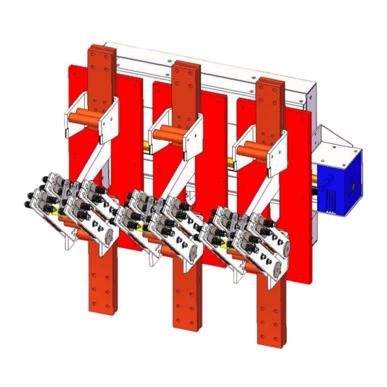
Page 16: Figure 8. Powlvac ® Enclosed Indoor Disconnect Switch Operating Mechanism
Enclosed Indoor Disconnect Switch IB-26100 ® Figure 8. PowlVac Enclosed Indoor Disconnect Switch Operating Mechanism a. Motor g. Slider b. Hex Rod End h. Ground Bus (Optional Open Position Grounding Contacts) c. Couplers (2) Threaded Rod d. Torque Limiter Gear Box (Right Angle) e. -
Page 17: Installation
Enclosed Indoor Disconnect Switch IB-26100 IV. INSTALLATION CAUTION A. RECEIVING THE SWITCH MUST BE LIFTED BY Upon receipt, remove any shipping material and ATTACHING LIFTING MEANS TO THE inspect the enclosed indoor disconnect switch for BASE OF SWITCH ONLY LIFTING THE damage that may have occurred during shipment SWITCH BY USING ANY OF THE HIGH- Check equipment received against the shipping... - Page 18 Enclosed Indoor Disconnect Switch IB-26100 The enclosed indoor disconnect switch If the enclosed indoor disconnect switch is stored should be stored in a clean location free from for any length of time, it should be inspected corrosive gases or fumes. Particular care periodically to see that rusting has not started and should be taken to protect the equipment from to ensure good mechanical condition.
-
Page 19: Maintenance
Enclosed Indoor Disconnect Switch IB-26100 MAINTENANCE Primary insulation, including the main contact supports and the insulating operating links, should also be cleaned Wipe clean with a dry lint-free A. GENERAL cloth or an industrial type wiper If dirt adheres A regular maintenance schedule should be and will not come off by wiping, remove it with established to obtain the best service and denatured alcohol... -
Page 20: Lubrication
Rheolube-368A should be used to lubricate moving parts of the operating mechanism Powell offers a complete lubrication kit (Powlube- 102) which contains all the lubricants required for maintaining the switch. Powered by Safety ®... -
Page 21: Renewal Parts
Enclosed Indoor Disconnect Switch IB-26100 VII. RENEWAL PARTS A. ORDERING Should any part require replacement due to wear or damage, order renewal parts from Powell Apparatus Service (PAS) When ordering parts, provide the following information: • Name of the ultimate user •... -
Page 22: Table B. Renewal Parts
Enclosed Indoor Disconnect Switch IB-26100 Table B. Renewal Parts Description Catalog Number Illustration Acme Rod 35351P00000004 Gear Box RVO75 (Motovario Mfg.) Motor S13421 Operating Link 35351P00005147 Limit Switch Assembly (Specific to Order number) Moving Contact Spring R042203P100 Setting Gauge PowlVac Lubrication Kit Powlube-102 Powered by Safety ®... - Page 23 Inspection and Cleaning isolation Installation qualified personnel handling Ordering parts racking receiving transport or install storage Safety labels Parts Instruction Bulletin Standards Powell Electrical Systems, Inc. Web site Storage Introduction purpose Qualified personnel scope Weight Powered by Safety ®...
- Page 24 Powered by Safety Powell Electrical Systems, Inc. ® Tel: 713.944.6900 • Fax: 713.947.4453 Powell Electrical Manufacturing Visit us at www.powellind.com PO Box 12818 • Houston, TX • 77217 Email us at info@powellind.com ©2005 Powell Industries, Inc. • All rights reserved.
Need help?
Do you have a question about the PowlVac 63kA and is the answer not in the manual?
Questions and answers