
Subscribe to Our Youtube Channel
Related Manuals for Powell LVSWGR-AR


Summary of Contents for Powell LVSWGR-AR
- Page 1 DRAFT Powered by Safety ® 01.4IB.26263B Low Voltage Arc Resistant Switchgear Equipped with Magnum DS Circuit Breakers...
- Page 2 Low Voltage Arc Resistant Switchgear (LVSWGR-AR®) 01.4IB.26263B Equipped with Magnum DS Circuit Breakers Contact Information Powell Electrical Systems, Inc. powellind.com info@powellind.com Service Division PO Box 12818 Houston, Texas 77217-2818 Tel: 713.944.6900 Fax: 713.948.4569 Powered by Safety ®...
- Page 3 01.4IB.26263B Signal Words Qualified Person As stated in ANSI Z535.4-2007, the signal word is For the purposes of this manual, a qualified a word that calls attention to the safety sign and person, as stated in NFPA 70E®, is one who has designates a degree or level of hazard seriousness.
- Page 4 Low Voltage Arc Resistant Switchgear (LVSWGR-AR®) 01.4IB.26263B Equipped with Magnum DS Circuit Breakers This page is intentionally left blank. Powered by Safety ®...
-
Page 5: Table Of Contents
01.4IB.26263B Contents Ch 1 General Information ....................1 A. S ................................2 cope B. p ................................2 urpoSe c. I ....................2 nStructIon ulletInS vAIlABle lectronIcAlly Ch 2 Safety ........................3 A. S ............................3 ondItIon B. S ...............................3 Afety uIdelIneS c. G ................................4 enerAl d. S ................................4 pecIfIc e. - Page 6 Low Voltage Arc Resistant Switchgear (LVSWGR-AR®) 01.4IB.26263B Equipped with Magnum DS Circuit Breakers Contents Ch 5 Maintenance ......................23 A. G ................................. 23 enerAl B. o ........................23 verAll AIntenAnce rocedureS 1) Equipment ....................................24 2) Bus Insulation ..................................24 3) Mechanisms ....................................24 4) Primary Disconnect Device Contacts ..........................24...
- Page 7 01.4IB.26263B Figures Figure 1 Powell Low Voltage, Arc Resistant Switchgear ..........8 Figure 2 Removing the Circuit Breaker from the Switchgear ........9 Figure 3 Switchgear on Lifting Crane ................11 Figure 4 Chain/Cable Sling Installation ..............14 Figure 5 Base View .....................15 Figure 6 Side View ......................16...
- Page 8 01.4IB.26263B Equipped with Magnum DS Circuit Breakers Tables Table A Powell Low Voltage Arc Resistant Switchgear Ratings - Type 2B ......7 Table B Magnum DS Circuit Breaker Ratings ..............7 Table C Low Voltage Arc Resistant Switchgear Dimensions ..........16 Table D Bolt Torque Values for Powell Low Voltage Metal-Enclosed Switchgear ..19 Table E Accessories ......................29...
-
Page 9: Ch 1 General Information
The information in this instruction bulletin is not intended to explain all details or variations of the Powell equipment, nor to provide for every possible contingency or hazard to be met in connection with installation, testing, operation, and maintenance of the equipment. For additional information and instructions for particular problems, which are not presented sufficiently for the user’s purposes, contact Powell at 1.800.480.7273. -
Page 10: S Cope
Low Voltage Arc Resistant Switchgear (LVSWGR-AR®) 01.4IB.26263B Equipped with Magnum DS Circuit Breakers A. S The illustrations contained in this document cope may not represent the exact construction The information in this instruction bulletin details of each particular type of switchgear describes Powell low voltage arc resistant section. -
Page 11: Ch 2 Safety
The rules are intended to cover only some of the (82.02.01)/UL 61010-1, Safety Requirements important aspects of personnel safety related to for Electrical Equipment for Measurement, Powell low voltage arc resistant switchgear. Control, and Laboratory Use - Part 1: General Requirements, for rating and design requirements for voltage measurement and test instruments intended for use on electrical systems 1000 V and below. -
Page 12: G Eneral
Low Voltage Arc Resistant Switchgear (LVSWGR-AR®) 01.4IB.26263B Equipped with Magnum DS Circuit Breakers c. G d. S enerAl pecIfIc 1. Only qualified personnel trained in 1. DO NOT WORK ON ENERGIZED the usage, installation, operation, and SWITCHGEAR. If work must be performed... -
Page 13: S Afety Abels
01.4IB.26263B e. S Afety ABelS The equipment described in this document has DANGER, WARNING, CAUTION, and instruction labels attached to various locations. All equipment DANGER, WARNING, CAUTION, and instruction labels shall be observed when the circuit breaker is handled, operated, or maintained. -
Page 14: Ch 3 Equipment Description
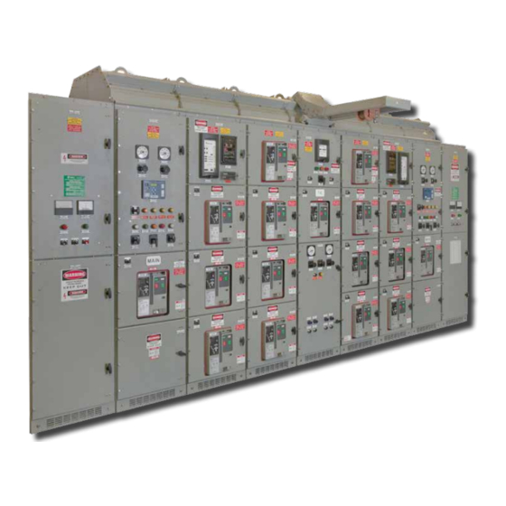
Low Voltage Arc Resistant Switchgear (LVSWGR-AR®) 01.4IB.26263B Equipped with Magnum DS Circuit Breakers Ch 3 Equipment Description Powell low voltage, arc resistant switchgear for Magnum DS LVPCB circuit breakers consists of A. G multiple sections, fastened together as a single enerAl group (Figure 1). -
Page 15: Atings
01.4IB.26263B B. r AtInGS Table A Powell Low Voltage Arc Resistant Switchgear Ratings - Type 2B Short Time Current Short Circuit Current Maximum Arc Fault Voltage Current Main Bus Riser Bus Main Bus Riser Bus (volts) (kA) (kA) (kA) (kA) (kA) 85(.5s) -
Page 16: Figure 1 Powell Low Voltage, Arc Resistant Switchgear
Low Voltage Arc Resistant Switchgear (LVSWGR-AR®) 01.4IB.26263B Equipped with Magnum DS Circuit Breakers Figure 1 Powell Low Voltage, Arc Resistant Switchgear Powered by Safety ® Equipment Description... -
Page 17: Figure 2 Removing The Circuit Breaker From The Switchgear
Note: Breaker maintenance covers for compartments not equipped with circuit breakers are not shown for illustrative purposes only. a. Powell Overhead Lifting Device b. Overhead Lifting Device Handle c. Overhead Lifting Device Cable d. Instrument Comparment e. Lifting Device Yoke f. -
Page 18: Ch 4 Installation
The switchgear is shipped with the circuit values. See Table D, Bolt Torque Values for Powell breakers installed unless other instructions Medium Voltage Metal-Enclosed Switchgear. are given. If the circuit breakers are shipped installed, they are done so in the open and B. -
Page 19: Lifting The Switchgear
01.4IB.26263B d. S 1) Lifting the Switchgear torAGe Shipping and storage of electrical equipment The maximum shipping section width is requires measures to prevent the deterioration 102 inches. The equipment should be lifted of the apparatus over a long unused period. using an appropriately rated overhead crane. -
Page 20: P Ositioning The M Etal -E Nclosed Switchgear
Low Voltage Arc Resistant Switchgear (LVSWGR-AR®) 01.4IB.26263B Equipped with Magnum DS Circuit Breakers 2. Equipment designed for outdoor exposure The recommended aisle space for the may be stored either in indoor or outdoor front and at the rear of the metal-enclosed storage locations. -
Page 21: P Reparation Of F Loor A Nchoring For I Ndoor M Etal -E Nclosed Switchgear
01.4IB.26263B Additional shipping members may have The floor channels should have a minimum been installed in the bus or primary area web dimension of 4 inches. The required to ensure against shipping damage. All quantity and location of the floor channels shipping members must be removed from is shown on the drawings furnished with the switchgear compartments. -
Page 22: Figure 4 Chain/Cable Sling Installation
Low Voltage Arc Resistant Switchgear (LVSWGR-AR®) 01.4IB.26263B Equipped with Magnum DS Circuit Breakers Figure 4 Chain/Cable Sling Installation Minimum 45˚ 45˚ Minimum 45˚ 45˚ Minimum 45˚ 45˚ Powered by Safety ® Installation... -
Page 23: Figure 5 Base View
01.4IB.26263B Figure 5 Base View 4.280 Note: The Cable Space Width is only contingent on the frame size. It has no bearing on the equipment depth and will be one of two dimensions shown in Table C Low Voltage Arc Resistant Switchgear Dimensions, C Cable Space, 46.375 Width. -
Page 24: Figure 6 Side View
Low Voltage Arc Resistant Switchgear (LVSWGR-AR®) 01.4IB.26263B Equipped with Magnum DS Circuit Breakers Figure 6 Side View Front Cable Compartment Compartment 111.751 94.120 50.906 Table C Low Voltage Arc Resistant Switchgear Dimensions Equipment Rear Cable Space Equipment Front Depth Compartment... -
Page 25: G Rounding
01.4IB.26263B G. G It is recommended that the connection to the roundInG station ground have a cross section of 500,000 Before power connections can be made, the circular mils (240mm ) or greater if the soil switchgear vertical sections must be grounded. in which it is buried is of such character as to A ground bus is furnished with lugs at each cause appreciable corrosion. -
Page 26: Main B Us Assembly I Nsulation
Low Voltage Arc Resistant Switchgear (LVSWGR-AR®) 01.4IB.26263B Equipped with Magnum DS Circuit Breakers 2. Join the clean contact surfaces by using the 4. All field assembled primary conductor hardware provided. joints and terminations must be insulated before the operating voltage is applied. -
Page 27: Applying Pvc Boots
01.4IB.26263B Wear protective gloves and goggles and Table D Bolt Torque Values for Powell clean the main bus bar in a well ventilated Low Voltage Metal-Enclosed Switchgear area. Bolt Torque Bolt Dimensions Head Ft-Lbs Kg-M Vacuum and wipe dirt or other foreign... -
Page 28: C Ontrol C Ables
Low Voltage Arc Resistant Switchgear (LVSWGR-AR®) 01.4IB.26263B Equipped with Magnum DS Circuit Breakers k. c M. I ontrol ABleS nSpectIon And eStInG When control conduits enter the unit from For assistance with testing and inspection below, the conduit should not extend more contact the Powell Service Division at than 1 inch above the floor. -
Page 29: Figure 8 Main Bus Splice
01.4IB.26263B Figure 8 Main Bus Splice Typical Channel-Type Main Bus Connection a. Channel Splice (Upper) b. Main Bus Splice c. Main & Riser Bus Connection d. Nut Plate (Inner) (Copper with 1/2” Press Nut) e. 1/2” Flat Washer f. 1/2” Split Ring Lock Washer g. -
Page 30: Testing
Low Voltage Arc Resistant Switchgear (LVSWGR-AR®) 01.4IB.26263B Equipped with Magnum DS Circuit Breakers Figure 9 Plenum Vent 2) Testing The following tests shall be completed before placing the switchgear into operation: a. A megger test shall be made to ensure... -
Page 31: Ch 5 Maintenance
However, this enerAl insulation, in most instances requires a certain Contact Powell Service Division for assistance amount of air gap between phases and to in performing maintenance or setting up a ground, which completes the insulation. -
Page 32: Equipment
Low Voltage Arc Resistant Switchgear (LVSWGR-AR®) 01.4IB.26263B Equipped with Magnum DS Circuit Breakers The switchgear lineup and connections should Only use denatured alcohol or isopropyl be given the following overall maintenance at alcohol to clean the insulation. Wear least once a year: protective gloves and goggles and clean the main bus bar in a well ventilated area. -
Page 33: Control Contacts
01.4IB.26263B 5) Control Contacts 9) Battery and Charging Equipment Contacts should be inspected and dressed The control battery is such an important or replaced when the surface becomes accessary to the switchgear operation seriously pitted. Unless repetitive duty has that it must be given special periodic been experienced, little attention should be attention if it is to have a long life of reliable required. -
Page 34: Breaker Maintenance Cover
Low Voltage Arc Resistant Switchgear (LVSWGR-AR®) 01.4IB.26263B Equipped with Magnum DS Circuit Breakers 12) Breaker Maintenance Cover 13) Records When the breaker is temporarily removed The condition of each switchgear unit at from the compartment for service, install the time of inspection should be listed in... -
Page 35: A Bnormal Onditions
01.4IB.26263B c. A BnorMAl ondItIonS Local atmospheric conditions such as high humidity, salty atmosphere, corrosive gases, heavy dust, extreme heat, or severe operating conditions, are considered to be abnormal, and more frequent equipment inspections are required. A series of quarterly inspections should be performed to analyze the effect of local abnormal conditions on equipment. -
Page 36: Ch 6 Replacement Parts
Low Voltage Arc Resistant Switchgear (LVSWGR-AR®) 01.4IB.26263B Equipped with Magnum DS Circuit Breakers Ch 6 Replacement Parts B. r ecoMMended eneWAl ArtS A sufficient amount of renewal parts should be A. o rderInG nStructIonS stored to enable the prompt replacement of any worn, broken or damaged part. -
Page 37: Table E Accessories
The numbers in the ( ) indicate the number of pieces or the length of cable included. (*) Ordered in quantities of foot. One (1) Breaker Maintenance Cover is shipped with each line-up, contact Powell for additional covers. Powered by Safety ®... - Page 38 Magnum DS Circuit Breakers September 2015 Powered by Safety ® Powell Electrical Systems, Inc. Tel: 713.944.6900 • Fax: 713.948.4569 Service Division - Houston powellind.com PO Box 12818 • Houston, TX • 77217 info@powellind.com ©2006 Powell Industries, Inc. • All rights reserved.
Need help?
Do you have a question about the LVSWGR-AR and is the answer not in the manual?
Questions and answers