Table of Contents
Advertisement
Quick Links
Advertisement
Table of Contents

Related Manuals for wilson & bradley CINETTO VOLO


Summary of Contents for wilson & bradley CINETTO VOLO
- Page 1 CINETTO VOLO (PS48.2) B-Moved Assembly instructions...
-
Page 2: Safety Instructions
SAFETY INSTRUCTIONS Safety guidelines of “B-MOVED" system Intended use “B-Moved” control system by Cinetto is exclusively intended to move sliding doors for wardrobes or for walk-in clo- sets. The maximum weight limit of each door, unless otherwise noted, is specifi ed on the technical datasheet of each compatible sliding system by Cinetto. -
Page 3: Limitation Of Liability
Limitation of liability Using and operating “B-Moved” in accordance with the technical datasheet of each compatible sliding system is man- datory. Any variation, manipulation, change of environment of use or improper application exclude Cinetto F.lli s.r.l. from any liability for direct or indirect damage. “B-Moved”... - Page 4 tial requirements of article 6 of Directive 2014/30/EU EN 301 489-3 V2.1.0 ElectroMagnetic Compatibility (EMC) standard for radio equipment and services; Part 3: Specifi c conditions for Short-Range Devices (SRD) operating on frequencies between 9 kHz and 246 GHz; Harmonised Standard covering the essential requirements of article 3.1(b) of Directive 2014/53/EU EN 300 220-2 V3.1.1 Short Range Devices (SRD) operating in the frequency range 25 MHz to 1 000 MHz;...
- Page 5 Italiano English Français Italiano English Tutte le misure espresse in questo opuscolo All dimensions in this leafl et are stated in Toutes les mesures indiquées dans cette bro- Tutte le misure espresse in questo opuscolo All dimensions in this leafl et are stated in sono in millimetri.
- Page 6 Working requests for the doors Lavorazioni richieste per le ante Working requests for the doors Usinage nécessaire pour les portes 2 x locating holes Verarbeitungsanforderungen für die Türen 7.5mm wide x 11mm deep Laboreo necesario para las puertas Ø7,5x11 Ø7,5x11 (-0 +0,5) (-0 +0,5) option...
-
Page 7: Istruzioni Di Montaggio
Istruzioni di montaggio Assembly instructions Assembly instructions Instructions de montage Montageanleitungen Instrucciones de ensamblaje... - Page 9 Schemi di posizionamento dei fermi di sicurezza, supporti per fi ssaggio, staff e e pioli. Scegliere il tipo di binario superiore / Choose the type of upper rail / Scegliere il tipo di binario superiore / Choose the type of upper rail / Assembly instructions Safety stop, fastening brackets, brackets and pegs positioning schemes.
- Page 10 Fissare il profi lo as- Fix the assembled profi le Fixer le profi l assemblé Das zusammengebaute Fijar el perfi l montado semblato per il si- for B-moved system to the pour le système B-moved Profi l für das System para el sistema B-moved stema B-moved all' Fix the assembled profile for B-moved system...
- Page 11 Fissare il binario Fix the lower rail to the Fixer le rail inférieur au Befestigen Sie die untere Fijar la guía inferior al inferiore al mobile wardrobe according to meuble selon le mode Schiene an den Schrank mueble según vuestra secondo la modalità...
- Page 12 Schemi di posizionamento dei fermi di sicurezza, supporti per fi ssaggio, staff e e pioli. Schemi di posizionamento dei fermi di sicurezza, supporti per fi ssaggio, staff e e pioli. Safety stop, fastening brackets Safety stop, fastening brackets, brackets and pegs positioning schemes. Safety stop, fastening brackets, brackets and pegs positioning schemes.
- Page 13 4 mm Sistema di fi ssaggio dall’alto. 90° 90° Locking system from the top. Système de fi xation par le haut. Locking system from the top Befestigungssystem von der Spitze. Sistema de fi jación desde la parte superior. 4 mm...
- Page 14 4 mm...
- Page 15 option 5 mm DISTANZIATORE PER ANTE 43 mm DOORS SPACER DOOR SPACER ENTRETOISE POUR PORTES 22 mm SPACER FÜR TÜREN ESPACIADOR PARA PUERTAS 22 - 43...
- Page 16 PARACOLPI PER SOLA ANTA INTERNA SX - UTILIZZO CON ARMADIO A 3 ANTE BUMPERS ONLY FOR LEFT INTERNAL DOOR - USABLE WITH 3 DOORS WARDROBE BUTOIR POUR UNE PORTE INTÉRIEUR GAUCHE - À UTILISER AVEC ARMOIRE 3 PORTES BUMPERS ONLY FOR LEFT INTERNAL DOOR - USABLE WITH 3 DOORS WARDROBE ANSCHLAG NUR FÜR DIE LINKE TÜR - VERWENDET NUR FÜR DIE DREITURIGEN SCHRANK PARAGOLPE PARA LA PUERTA INTERNA –...
- Page 17 Anta regolata troppo in alto. Door adjusted too high. Porte réglé trop haut. Tür zu hoch eingestellt. Puerta demasiado alto. Anta regolata troppo in basso. Door adjusted too low. Porte réglé trop bas. Tür zu niedrig eingestellt. Puerta demasiado bajo.
- Page 18 SISTEMA ANTISCARRUCOLAMENTO Ruotare l’antiscarrucolamento prima di togliere l’anta. ANTIDERAILING DEVICE Rotate the antiderailing device before remove the door. SYSTÈME ANTI-DÉRAILLEMENT Tourner l’anti-déraillement avant d’enlever la porte. ENTGLEISUNGSSCHUTZ- SYSTEM Vor dem Entfernen der Tür das Entgleisungsschutzsystem drehen. SISTEMA ANTIDESCARRILAMIENTO Gire el antidescarrilamiento antes de sacar la puerta. ±3 mm +3 mm 4 mm...
- Page 19 Close the door and positioning the lower lock. Chiudere l’anta e Close the door and Fermer la porte et pla- Die Tür schließen und Cerrar la puerta y co- posizionare il fer- positioning the lower cer l’arrêt inférieur. den unteren Anschlag locar el tope inferior.
- Page 20 Confi gurazioni armadio Schemi di posizionamento dei fermi di sicurezza, supporti per fi ssaggio, staff e e pioli. Wardrobe configurations Wardrobe confi gurations Safety stop, fastening brackets, brackets and pegs positioning schemes. Confi guration armoire Positionnement des butées de sécurité, supports de fi xation, supports et goupilles. Schrank konfi...
- Page 21 CONFIGURAZIONE CONFIGURATION CONFIGURATION CONFIGURATION KONFIGURATION CONFIGURACIÓN...
- Page 22 CONFIGURATION *Il tipo di connet- *The type of bracket *Le type de support *Die Art der Klammer *El tipo de soporte tori dipende dalla depends on the con- dépend de la con- hängt von der gewählten depende de la con- *The type of bracket depends on the configuration chosen configurazione fi...
- Page 23 CONFIGURATION...
- Page 24 CONFIGURATION CONFIGURATION REMOTE CONTROL MOTE CONTROL CONFIGURATION NFIGURATION...
- Page 25 CONFIGURAZIONE CONFIGURATION CONFIGURATION CONFIGURATION KONFIGURATION CONFIGURACIÓN *Apertura dell' *Central door ope- *Ouverture de la por- *Mitteltüröffnung nur *Apertura anta centrale solo ning just to the left. te centrale seulement nach links. puerta central sólo a *Central door opening just to the left verso sinistra.
- Page 26 CONFIGURATION 4 mm 4 mm...
- Page 27 CONFIGURATION 4 mm...
- Page 28 CONFIGURATION...
- Page 29 CONFIGURATION...
- Page 30 Höhe Abstand z Dicke Überlappu CONFIGURATION CONFIGURATION Die Bilder und Besc spektes sind nur zu Die Firma kann, in erungen und Verbe kündigung vornehm REMOTE CONTROL MOTE CONTROL CONFIGURATION NFIGURATION...
- Page 31 Tiefe altura distancia entre centros Höhe distancia entre centros hen den Zentren espesor Abstand zwischen den Zentren espesor superposición Fissaggio dei cablaggi Dicke superposición Überlappung Las imagines y las descripciones de este Hold wiring Hold wiring Las imagines y las descripciones de este bungen dieses Pro- folleto solo se fechas a titulo informativo.
- Page 33 Connettore per ingresso ausiliario di controllo Connector for auxiliary control input Connecteur pour entrée de commande auxiliaire Connector for auxiliary control input Anschluss für zusätzlichen Steuereingang Conector para entrada de control auxiliar Smart Home switch device N.O. Input apertura/chiusura 1 signal ~0,5s Input opening/closing 1 signal ~0,5s...
- Page 35 WARNINGS AND USE INSTRUCTIONS 1. System use guidelines 1.1 General description of the ‘B-Moved’ system ‘B-Moved’ is an electronically-controlled mechanical system for moving cabinet or similar doors on the special sliding arrangements indicated in the instructions. Each door is equipped with a movement bar, composed of a screw axially connected to an electric motor, which drives a lead nut attached to the door.
-
Page 36: Power Failure
control buttons for each confi guration are indicated in the respective installation and use instructions. 1.7 Door movement program Each door can be moved individually. If the door meets an obstacle while moving, it will automatically stop. If a door is stopped with a force contrary to its direction of movement, it stops and starts moving in the opposite direction. -
Page 37: Set-Up Operations
3. Set-up operations 3.1 Initial cabinet set-up Do not power the control unit until all motors have been connected. Connect all movement bar motors to the control unit according to the chosen cabinet confi guration. After connecting all the motors to the control unit according to instructions, manually bring the doors to their closed posi- tions. -
Page 38: Remote Control Pairing
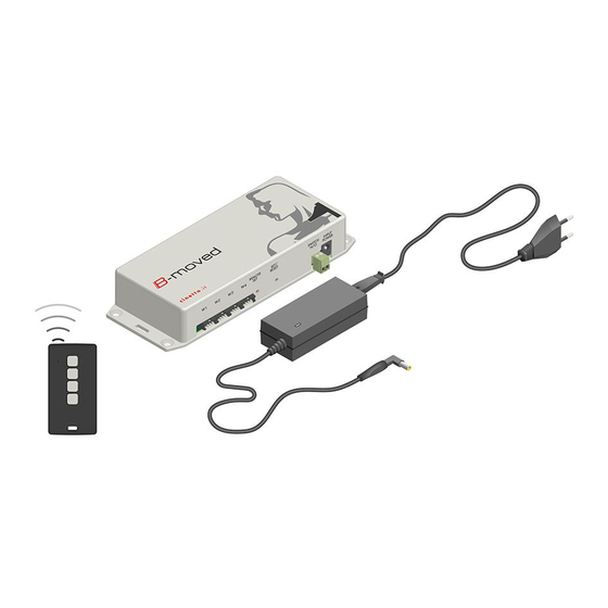
3.4 Remote control pairing In order to activate the pairing function, press and rele- ase the ‘REMOTE SET’ button on the control unit, after which a red LED will fl ash on the con- trol unit. Now long press (3 seconds) one of the active remote control but- tons. -
Page 39: Use Instructions
0 - 48 SWITCH DEVICE DEVICE DEVICE SOURCE 0 - 48V DEVICE MAX 2A SWITCH 3.6 Checks Check that each door moves correctly. Check that the system is effective in avoiding crushing, by introducing an object between the cabinet side and the closing door. Perform this checks in order to avoid any risk, damage or injury due to possible faults or malfunctioning of the system. - Page 40 and operate the motor until the door reaches its open position. In the event that the opening of a door is obstructed by another previously opened door, both doors will move simultaneously to free the opening. 4.2 Door closing The door closing command can be given by slightly pushing on the door or by using the remote control. Push the door a few millimetres in its closing direction and the system will automatically detect the displacement and operate the motor until the door reaches its closed position.
- Page 41 6. FAQ 6.1 Despite pressing the ‘SET/RESET’ button, the self-learning function is not activated Check the system power supply. Make sure the power jack and power supply adapter cable are properly inserted. 6.2 The self-learning function does not work on all cabinet doors Check that the motor to control unit connection has been made according to instructions and that the pins are properly inserted.
- Page 42 Check the appliance is connected properly, as indicated in Section 3.5. Remember that the switch does not supply an output voltage, and acts as a simple switch. Connect one of the 2 poles of the power supply to the switch to have the device controlled by the control unit. Check that the device is compatible with a maximum power supply of 48V and absorbs a maximum current of 2.1A.
Need help?
Do you have a question about the CINETTO VOLO and is the answer not in the manual?
Questions and answers