
Related Manuals for AKO PROPlus 3PH BASIC


Summary of Contents for AKO PROPlus 3PH BASIC
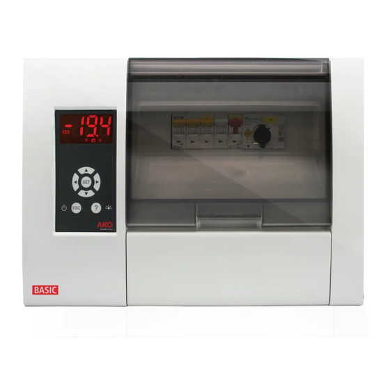
- Page 1 1569H042 Ed.03 AKO-1569x AKO-1569x-EVC PROPlus 3PH BASIC Electronic Panel User Manual...
-
Page 2: Table Of Contents
Complying with and enforcing the regulations applying to installations where our products are destined to be used is the responsibility of the installer and the customer. AKO Electromecànica accepts no liability for damage which may occur due to failure to comply with these regulations. -
Page 3: Presentation
Using the equipment without following the manufacturer's instructions may affect the device's safety requirements. To ensure that the device operates correctly, only probes supplied by AKO should be used. Between -40 ºC and +20 ºC, if the NTC probe is extended up to 1,000 m with minimum 0.5 mm² wire, the maximum deviation will be 0.25 ºC (Wire for probe extension ref. -
Page 4: Installation
1569H042 Ed.03 3.- Installation A.- Open and remove cover. 90º B.- Using the included template, make 4 holes in the wall and fasten the unit to the wall using the supplied screws. Make a hole in the bottom of the box to pass the cables through, and a suitable gland should be used to main the IP65 degree of protection. - Page 5 C.- Put on the cover, and arrange the wiring according to the diagrams enclosed. Connect the control hose (1), adjust the motor guard (Q1/Q3) and close the cover (2). AKO-15690/1/2/3, AKO-15690/1/2/3-EVC Motor guard adjustment (Q1): Put an ammeter clamp into one of the compressor's conductors. Start the compressor and check its consumption.
- Page 6 1569H042 Ed.03 ALL MODELS D.- Remove the front trims (A) and screw the cover on using the included screws (B). Then install the trims again.
-
Page 7: Recommendations
1569H042 Ed.03 4.- Recommendations Disconnect the voltage before carrying out any operations inside the electrical panel. All wiring should be according to current standards and should be carried out by authorised staff. Only carry out the wiring foreseen in the wiring diagrams. -
Page 8: Description
1569H042 Ed.03 5.- Description Temperatura Stand-by active mode Change of the Set Point active (see page 13) Continuous cycle active Defrosting in progress Cold room light active Fans active Compressor active* Alarm active Compressor or solenoid active** Electronic expansion valve Display controller Browser... -
Page 9: Messages
1569H042 Ed.03 6.2- Messages Flashing 0: Access code (Password) request You must enter the access code configured on L5 to execute the requested function (p. 19). See also parameter P2 (p. 25) Probe 1 or 2 faulty (open circuit, crossover or temperature outside the probe limits; NTC: -50 To 99 ºC). -
Page 10: Component Location
1569H042 Ed.03 6.- Component location Probe and communications terminal Protections Expansion valve Control cable connector controller (EVC) Contactors Transformer Control terminal Power supply terminal and expansion valve Earth control terminal ATTENTION: Make sure to turn of the equipment's power supply before handling it, as different areas may be energised. -
Page 11: Pressure Switch Wiring Options
7.- Pressure switch wiring options 7.- Pressure switch wiring options 7.- Pressure switch wiring options 7.- Pressure switch wiring options Combine high-low pressure controller (AKO-15690/1/2/3 - AKO-15690/1/2/3-EVC) Separate Low pressure controller per AC input (AKO-15690/1/2/3 - AKO-15690/1/2/3-EVC) Pressure controller equivalence FAN CONTROL... -
Page 12: Basic Configuration
1569H042 Ed.03 8.- Basic configuration The basic configuration menu allows the equipment to be configured for the most common applications. Press the SET key for 5 seconds to access it. If the access code is activated, a 2 digit code is requested (See page 19), if the code entered is not correct the unit will not enter programming. -
Page 13: Operation
1569H042 Ed.03 9.- Operation ducts. 9.1.- Compressor control probe 1 reaches the set NORMAL OPERATION ws the % icon while this mode is active. When the temperature in probe 1 reaches the set probe's differential (C1), point value (SP) plus the probe's differential (C1), COMP. - Page 14 1569H042 Ed.03 COMPRESSOR PROTECTION DELAY There are three types of delay, selectable by parameter C4, to protect the compressor. These delays prevent continuous compressor starts and stops due to sudden changes in temperature. OFF-ON (C4=0): Minimum compressor OFF time before each start-up. OFF-ON / ON-OFF (C4=1): Minimum time during which the compressor will remain ON and OFF in every cycle.
-
Page 15: Defrost Control
1569H042 Ed.03 9.2.- Defrost control Max. d1 FAN START DELAY “DEF” MESSAGE DRIP CONTROL DEFROST CONTROL CONTROL DEFROST TIME ºC SP+C1 time Defrost start-up Defrost is initiated if: -Time scheduled in parameter d0 has passed since the beginning of last defrost. -The N key is pressed for 5 seconds. -
Page 16: Fan Control
1569H042 Ed.03 al button, connecting it to one of the digital inputs Other parameters Parameter d5 allows users to specify if the unit will (d5=1) or will not (d5=0) defrost when powered up (initial start-up or after a power failure). In case of choosing option YES (d5=1), the defrost will start after the delay time specified in d6. -
Page 17: Pump Down Function
1569H042 Ed.03 9.5.- Pump down function This function prevents compressor problems caused by movement of the refrigerant, using a stop/start technique of the unit controlled by liquid solenoid, the low pressure switch and the compressor. For this feature to be active, the auxiliary relay must be set as "Pump down" (P6=1). SHUTOFF When temperature probe 1 reaches the set point value (SP), the AUX 1 relay is deactivated by closing the liquid solenoid. -
Page 18: Alarms
1569H042 Ed.03 9.6.- Alarms The unit warns the user with a message on the screen of the activation of a relay or the activation of an acoustic signal in certain circumstances, according to the programming of the following parameters. Max/Min Temperature Alarm Shows the AH or AL message when the temperature in probe 1 reaches the value set in the A1 (maximum temperature) or A2 (low temperature) parameters. -
Page 19: Access Code (Password)
1569H042 Ed.03 Pump down malfunction error (Start up) Displays the LP message if a malfunction is detected when the installation is started up using the pump down manoeuvre. (See page 17). DOES NOT activate the alarm relay or the sound alarm, it is only shown on the display. Compressor safety chain alarm The ASC message is displayed if any component in the compressor's safety chain is triggered (compressor motor guard, thermistors or high pressure controller). -
Page 20: Parameter Transfer
1569H042 Ed.03 10.- Parameter transfer This function allows transferring the programmed parameters from one device to others, using the AKO-D14918 programming key. This will save a lot of time when configuring similar devices. Requires the use of the AKO-80018 power supply for the programming key. -
Page 21: Connectivity
The unit has a port for RS485 date connection (MODBUS), which can be managed using a PC. Up to 127 units can be connected to a PC with AKONet (AKO-5010), or to the AKO-5011 web server. Each of these units should have a different MODBUS address, that is defined using the P5. -
Page 22: Advanced Configuration
1569H042 Ed.03 12.- Advanced configuration Using the advanced configuration menu, you can set ALL the equipment's parameters. The parameters are grouped into 6 sections depending on their function. Press the N + Q keys for 10 seconds to access it. If the access code is activated, a 2 digit code is requested (See page 19), if the code entered is incorrect the unit will not enter programming mode. -
Page 23: Parameters
1569H042 Ed.03 12.3.- Parameters The parameters are grouped into 6 sections depending on their function. Press the N + Q keys for 10 seconds to access it. The Def. column shows factory-set default parameters. Temperature values are expressed in ºC. (Equivalent temperature in ºF) Level 1.- REGULATION AND CONTROL Description Units... - Page 24 1569H042 Ed.03 Level 1.- DEFROST CONTROL Description Units Max. (h.) d0 Defrost frequency (Time between two starts) (Page 15) (min.) d1 Maximum defrost duration (0=defrost deactivated) (Page 15) Type of message during defrost: (Page 15) 0=Current temperature; 1=Temperature at start of defrost; 2=Display dEF message (min.) Maximum duration of message (Time added at the end of the defrost process) (Page15)
- Page 25 1569H042 Ed.03 Level 1.- ALARM CONTROL Description Units Max. A0 Configuration of temperature alarms (Page 18): 0=Relative to SP 1=Absolute A1 Maximum alarm probe 1 (must be greater than SP) (Page 18) (ºC/ºF) 99,0 99,0 A2 Minimum alarm probe 1 (must be greater than SP) (Page 18) (min.) A3 Temperature alarm delay during start-up (Page 19) (min.)
- Page 26 PU Program version (Information) Pr Program revision (Information) EP Exit Level 1 Default parameters according to models Parameter Modelos 0=Deactivated 1=Pump down 1=Alarm AKO-15690/1/2/3 AKO-15697 0=Deactivated 2= Same compressor status 1=Alarm 2= External alarm 2= Same compressor status 1=Alarm AKO-15699/699-1...
-
Page 27: Technical Specifications
Resolution, setting and differential ........................0.1 ºC Thermometric precision..........................± 1 ºC Precision of the NTC probe at 25 ºC ......................± 0.4 ºC Input for NTC probe ..........................AKO-14901 Maximum input power in the operation ......................30 VA Working ambient temperature......................-5 ºC to 40 ºC Storage ambient temperature ......................–30 ºC to 70 ºC... - Page 28 AKO ELECTROMECÁNICA , S.A.L. Avda. Roquetes, 30-38 08812 • Sant Pere de Ribes. Barcelona • Spain. Tel.: +34 902 333 145 Fax: +34 938 934 054 www.ako.com We reserve the right to supply materials that might vary slightly to those described in our Technical Sheets. Updated information is available on our website.
Need help?
Do you have a question about the PROPlus 3PH BASIC and is the answer not in the manual?
Questions and answers