
Related Manuals for AKO PROPlus 3PH


Summary of Contents for AKO PROPlus 3PH
- Page 1 1565H042 Ed.03 AKO-1565x AKO-1568x AKO-1565x-1 AKO-1565x-3 PROPlus 3PH Electronic Panel User Manual...
-
Page 2: Table Of Contents
Complying with and enforcing the regulations applying to installations where our products are destined to be used is the responsibility of the installer and the customer. AKO Electromecànica accepts no liability for damage which may occur due to failure to comply with these regulations. -
Page 3: Presentation
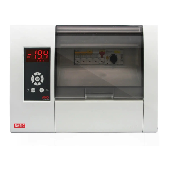
1565H041 Ed.03 1.- Presentation PROPlus 3PH is the global electronic solution to manage positive and negative cold room stores, in combination with: Standard condensing units Ÿ Streamlined condensing units Ÿ Or as a service panel in decentralised systems. Ÿ It has a high IP65 degree of protection for installation in damp environments. It is easy to install thanks to its new connection strip and intuitive menus with help texts that make programming easier by using its backlit LCD display. -
Page 4: Versions And References
1565H041 Ed.03 2.- Versions and references AKO-15650 2,5 - 4 A 7.000 W AKO-15651 4 - 6,3 A AKO-15652 6,3 - 10 A 10.200 W AKO-15653 10 - 16 A AKO-15680 2,5 - 4 A 7.000 W AKO-15681 4 - 6,3 A... -
Page 5: Installation
1565H041 Ed.03 3.- Installation A.- Open and remove cover. 90º B.- Using the included template, make 4 holes in the wall and fasten the unit to the wall using the supplied screws. Make a hole in the bottom of the box to pass the cables through, and a suitable gland should be used to main the IP65 degree of protection. - Page 6 C.- Put the cover on, and make the wiring according to the diagrams enclosed. Connect the battery (1), the control cable (2), adjust the motor guard (Q1/Q2/Q3) and close the cover (3). AKO-1565x, AKO-1568x, AKO 1565x-1 Motor guard adjustment (Q1): Put an ammeter clamp into one of the compressor's conductors. Start the compressor and check its consumption.
- Page 7 1565H041 Ed.03 AKO-15651-3 AKO 15652-3 AKO-15653-3 Motor guard adjustment Q1: Put an ammeter clamp into one of the compressor's conductors. Start the compressor and check its consumption. Set the motor guard (Q1) according to the obtained value. The set value should never be higher than the consumption indicated by the manufacturer.
-
Page 8: Recommendations
1565H041 Ed.03 4.- Recommendations Disconnect the voltage before carrying out any operations inside the electrical panel. All wiring should be according to current standards and should be carried out by authorised staff. Only carry out the wiring foreseen in the wiring diagrams. -
Page 9: Description
1565H041 Ed.03 5.- Description Date Battery status Loading finished Time Day of Loading the week Temperature Faulty or not connected (flashing) Status indicators Display Browser Escape key Help key Safety cover Electrical protections 5.1.- Quick access to functions Pressing it for 5 seconds activates or Pressing it for 5 seconds allows changing the deactivates the defrost. -
Page 10: Status Leds
1565H041 Ed.03 5.2.- Status LEDs Permanent: Compressor relay active. Permanent: Fan relay activated. Flashing: It must be activated, but it is not Flashing: It must be activated, but it is not due to a parameter. due to a parameter. Defrost ended by time (See page 18). Defrost relay activated. -
Page 11: Component Location
1565H041 Ed.03 6.- Component location Probe and communications terminal Protections Battery connector Control cable connector Phase detector Contactors Insulation transformer Control terminal Earth Power supply terminal terminal ATTENTION: Make sure to turn of the equipment's power supply before handling it, as different areas may be energised. -
Page 12: Pressure Switch Wiring Options
7.- Pressure switch wiring options 7.- Pressure switch wiring options 7.- Pressure switch wiring options 7.- Pressure switch wiring options (Not available in AKO-15658/59) (Not available in AKO-15658/59) (Not available in AKO-15658/59) (Not available in AKO-15658/59) (Not available in AKO-15658/59) -
Page 13: Programming Menu
1565H041 Ed.03 8.- Programming menu 8.- Programming menu It allows configuring the operating parameters. The programming menu allows adjusting the unit's parameters to the installation's needs. The programming menu allows adjusting the unit's parameters to the installation's needs. Press the SET key for 5 seconds to access the programming menu. If the access code is activated, a 2 digit code is Press the SET key for 5 seconds to access the programming menu. - Page 14 1565H041 Ed.03 Connected sensors Choose the correct option according to the no. of probes connected: Sensor 1: If it has just one control probe. Defrost will end by time. Ÿ Sensor 1 and 2: If it has two probes, a control probe and another one for defrost (evaporator). Ÿ...
- Page 15 1565H041 Ed.03 Delay at Start-up They allow delaying the start up of the installation when it receives electricity. This parameter prevents continuous stoppages and start-ups of the installation in exceptional situations, for example, after a power cut, in test periods or during the commissioning of the installation.
-
Page 16: Operation
Hour: It times the energy saving mode start hour. Ÿ Minute: It times the energy saving mode start minute. Ÿ *In the panels AKO-15658 / 15659, the liquid solenoid is controlled instead of the compressor. - Page 17 If the door stays open longer than the value programmed in the Inact. with door open parameter, the compressor/solenoid* will return to normal operation (See page 25). *In the panels AKO-15658 / 15659, the liquid solenoid is controlled instead of the compressor.
-
Page 18: Defrost Control
Signals end defrost time parameter is configured in “Yes”. We press the N key for 5 seconds. Ÿ REMARK: If the Defrost duration is configured to 0, no defrosts are carried out. *In the panels AKO-15658 / 15659, the liquid solenoid is controlled instead of the compressor. - Page 19 This function allows activating the defrost of the unit using an external button, connecting it to one of the digital inputs that must be configured as "remote defrost”. *In the panels AKO-15658 / 15659, the liquid solenoid is controlled instead of the compressor.
-
Page 20: Fan Control
of probe 2 (evaporator). each compressor stop. 1565H041 Ed.03 during the defrost. s before starting the fans up, at the end of a defrost. 9.3.- Fan control d when the cold room's door is opened (this require COMP. n the Inact. with door open parameter, the fan Only if “Stop if compressor OFF?”=Yes VENT. -
Page 21: Pump Down Function
1565H041 Ed.03 9.5.- Pump down function This function foresees problems in the compressor caused by movements of coolant, using a stop/start technique of the installation, controlled via the liquid solenoid, the low pressure controller and the compressor itself. The auxiliary relay must be configured as "Pump down control" (default configuration), the liquid solenoid must be connected to the 1 and 2 terminals and there must be a low pressure controller connected as indicated in the diagrams. -
Page 22: Alarms
1565H041 Ed.03 activation of a relay or the 9.6.- Alarms The unit warns the user with a message on the screen of the activation of a relay or the ing to the programming of activation of an acoustic signal in certain circumstances, according to the programming of the following parameters: Alarm configuration It defines how the values of the different temperature alarms are defined:... -
Page 23: Data Logging
1565H041 Ed.03 Defrost finished by time alarm Defrost finished by time alarm The icon I is displayed when a defrost ends for maximum time. (The Signal end defrost time must be configured as The icon I is displayed when a defrost ends for maximum time. (The Signal end defrost time must be configured as “Yes”). -
Page 24: Haccp Logging
1565H041 Ed.03 -Data display It displays the data logged in the selected block on the screen. Log no. Log date First log: 00 Last log: 95 Scrolling through Log time Log value logs The name of each block indicates the date and time of its first log, but when it is displayed, the first datum displayed is the last log of the block. -
Page 25: Advanced Configurations
1565H041 Ed.03 10 Advanced configurations 10.1.- Digital inputs Function of the digital inputs They allow the unit to react in certain external events, and their configuration depends on the component that is connected and has the following options: Input configuration (1 or 2): It defines the behaviour of digital input 1. Ÿ... -
Page 26: Auxiliary Relay
1565H041 Ed.03 10.2.- Auxiliary relay Auxiliary relay function. This menu is used to configure the different operating options of the auxiliary relay: AUX relay configuration: It defines the operation of the auxiliary relay. Ÿ Pump down control: It controls the liquid solenoid valve in the stop and start processes with pump ž... -
Page 27: Parameter Transfer
1565H041 Ed.03 11.- Parameter transfer This function allows transferring the programmed parameters from one device to others, using the AKO-D14918 programming key. This will save a lot of time when configuring similar devices. It requires the use of the power supply for the AKO-80018 programming key. -
Page 28: Connectivity
The unit has a port for RS485 date connection (MODBUS), which can be managed using a PC. Up to 127 units can be connected to a PC with AKONet (AKO-5010), or to the AKO-5012 web server. Each of these units should have a different MODBUS address, that is defined using the Communication address of the q menu. -
Page 29: Parameters
1565H041 Ed.03 13.- Parameters 13.- Parameters The programming menu allows adjusting the unit's parameters to the installation's The programming menu allows adjusting the unit's parameters to the installation's needs. needs. Press the SET key for 5 seconds to access the programming menu. If the access Press the SET key for 5 seconds to access the programming menu. - Page 30 1565H041 Ed.03 Description Page Units Max. Defrost at Start-up (min.) Defrost delay at Start-up Signals end defrost time Drip time (min.) FAN control Description Page Units Max. Fans stop temperature (controlled by probe 2) (ºC/ºF) –40.0 99.9 (Probe 2 should be active) Fans differential s2 (ºC/ºF) 20.0...
- Page 31 (Sec.) 1800 Pump down On delay (0=Deactivated) (Sec.) Press. controller config.: Combined HP-LP LP indep. AC input LP indep. digital input * See table page 34 **Parameter not available in AKO-15658/59; the AUX relay is configured as “same status compressor”.
- Page 32 1565H041 Ed.03 GENERAL STATUS Description Page Units Max. Access password (to parameters and set point) Password to Set Point Initial parameters (configures the default values and exits programming) Registry interval (min.) Communication address Connected sensors: Sensor 1 Sensor 1 and 2 Sensor 1 and 3 Sensor 1, 2 and 3 Sensors to be displayed Display mode:...
- Page 33 Parameter AKO-1565x-3 AKO-1565x-1 AKO-15659 AKO-15653-2 Input 2 configuration Disabled External alarm External alarm Aux. relay configuration Pump down control Equal compressor state Pump down control Press. controller config* Combined HP-LP Combined HP-LP *The AKO-15658/59 models do not have pressure switches.
-
Page 34: Technical Specifications
Resolution, setting and differential ........................0.1 ºC Thermometric precision..........................± 1 ºC Precision of the NTC probe at 25 ºC ......................± 0.4 ºC Input for NTC probe ..........................AKO-14901 Maximum input power in the operation ......................30 VA Working ambient temperature......................-5 ºC to 40 ºC Storage ambient temperature ......................–30 ºC to 70 ºC... - Page 35 1565H041 Ed.03...
- Page 36 AKO ELECTROMECÁNICA , S.A.L. Avda. Roquetes, 30-38 08812 • Sant Pere de Ribes. Barcelona • Spain. Tel.: +34 902 333 145 Fax: +34 938 934 054 www.ako.com We reserve the right to supply materials that might vary slightly to those described in our Technical Sheets. Updated information is available on our website.
Need help?
Do you have a question about the PROPlus 3PH and is the answer not in the manual?
Questions and answers