
Subscribe to Our Youtube Channel
Related Manuals for VeriFone Commander Site Controller


Summary of Contents for VeriFone Commander Site Controller
- Page 1 Commander Site Controller Software Installation Guide P/N: DOC149-004-01-B Revision: A00...
- Page 3 VeriFone, Inc. Sapphire, Topaz, HPV-20, Ruby Manager, Everest, E ID, Electronic Journal On-site, and Ruby Card are trademarks of VeriFone, Inc. in the U.S. and/or other countries. All other trademarks or brand names are the properties of their respective holders.
- Page 4 RADIO AND TV COMMUNICATIONS REQUIRING THE USER TO TAKE WHATEVER STEPS NECESSARY TO CORRECT THE INTERFERENCE. 2. THE COMMANDER SITE CONTROLLER COMPLIES WITH PART 68 OF THE FCC RULES. LOCATED ON THE BOTTOM PANEL OF THIS UNIT IS A LABEL THAT CONTAINS, AMONG OTHER INFORMATION, THE FCC REGISTRATION NUMBER AND RINGER EQUIVALENCE NUMBER (REN) FOR THIS UNIT.
- Page 5 Battery Charging Notification The unit should be powered up for at least 24 hours prior to initial application download. This is to prevent loss of data and to ensure that the battery pack is fully charged.
-
Page 7: Table Of Contents
Connections....... 9 Installing Commander Site Controller Software ..10 4. - Page 8 Commander™ Site Controller Software Installation Guide July 25, 2013...
-
Page 9: Introduction
Use of these expansion capabilities will be determined by VeriFone. System peripherals, such as fuel dispensers, dispenser card readers (DCRs), and car wash controllers connect directly to the Commander Site Controller. Site Management Suite (SMS) provides additional functionality with four separate software modules: Journal Browser ■... -
Page 10: Hardware And Software Requirements
Commander™ Site Controller Software Installation The Commander Site Controller contains the functionality of a V950™ to perform on-site upgrades. The addition of a router allows the Commander Site Controller Receive configurations remotely using available Internet protocols and ■ tools, including a Web browser interface. -
Page 11: Diagrams
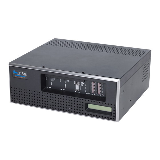
Front Panel CPU A Device Port LEDs (RX/TX) CPU A Indicators and Controls System Status Display Figure 2: Commander Site Controller - Front Panel System Status Display — The backlit, rectangular display on the front ■ panel of the Site Controller. -
Page 12: Cpu A Indicators And Controls
Reset Switch — For emergency use only and should never be touched ■ unless instructed by the VeriFone Technical Support Center. Service Console Port — This port is for use by a VeriFone Authorized ■ Service Contractor. It connects the PC/Laptop to the Site Controller. The connection communicates at 19200 bps 8N1. - Page 13 Commander™ Site Controller Software Installation Guide Dual 7-Segment Status Display — Displays codes showing the current ■ state of the system. (See the “Status Display Code List” in the Site Controller Software Installation Guide.) System Heartbeat LED — Pulsing red on and off indicates that the Site ■...
-
Page 14: Cpu A Device Port Leds (Rx/Tx)
Commander™ Site Controller Software Installation Guide CPU A Device Port LEDs (RX/TX) A3 Device Port LEDs for Serial Ports (For Future Use) A2 Device Port LEDs for Serial Ports A1 Device Port LEDs for Serial Ports Figure 4: Transmit/Receive Indicators for CPU A Serial Ports Device Port LEDs (RX/TX) —... -
Page 15: Rear Panel
Modem Port Ethernet Port Device Ports for CPU A Power Connector Figure 5: Commander Site Controller - Rear Panel Device Ports for CPU A — Serial Port Connections ■ for CPU A, Banks A1 and A2 Activity LEDS for CPU A — LEDs flicker to show ■... - Page 16 Commander™ Site Controller Software Installation Guide July 25, 2013...
-
Page 17: Software Installation
Download Software Download the Commander Site Controller Suite Software file from the VASC portal. The Commander Site Controller software is installed from a PC with the appropriate software stored on its hard drive or on a CD. The Commander Site Controller software suite contains three files: Executable Jar File (Petro_Suite_Installer.jar) -
Page 18: Installing Commander Site Controller Software
The Commander Site Controller permits installation of software only within the first five minutes after a reboot. 5. Allow the Commander Site Controller to come up fully. “A9” displays in the LED window. 6. On the PC, click Install. Do not powercycle or reboot the system during installation. - Page 19 Commander™ Site Controller Software Installation Guide 7. Browse to the directory where the files are stored. 8. Click and open the “overlay.zip” file. The installer package is unzipped and the installation begins. The following windows display during the installation. July 25, 2013...
- Page 20 Commander™ Site Controller Software Installation July 25, 2013...
- Page 21 Commander™ Site Controller Software Installation Guide July 25, 2013...
- Page 22 Commander™ Site Controller Software Installation July 25, 2013...
- Page 23 Commander™ Site Controller Software Installation Guide 9. Make note of the user name, secure ID#, and password and then click to confirm. The password will have one alphabetic character. Depending on the laptop font, it may be difficult to recognize a capital 'I' or 'O'. Note: If the information is not written down and is lost, you will need to call the help desk or re-install.
- Page 24 13. Do one of the following three common choices (a, b, or c) that matches your Hard Disk Drive configuration. a. Use the drop-down menu and select [FCC] if the HDD is not formatted and is in the Commander Site Controller and then click OK. July 25, 2013...
- Page 25 Commander™ Site Controller Software Installation Guide b. Use the drop-down menu. Select [MIF] if the HDD is to be used for V950SC applications and is required to be formatted. Click [OK]. Note: If there is no need to recover data from the HDD, choose [MIF].
- Page 26 Commander™ Site Controller Software Installation c. Use the drop-down menu. Select [KCC] if the HDD is already enabled and formatted. Click [OK]. July 25, 2013...
- Page 27 Commander™ Site Controller Software Installation Guide 14. If displayed, click [Yes] to format the HDD. July 25, 2013...
- Page 28 Commander™ Site Controller Software Installation 15. If the installation fails, the following windows display. July 25, 2013...
- Page 29 The installation can also fail for the following reasons. – The diagnostic (diag) switch is in the down position. See the Diagrams chapter. – The Commander Site Controller was not rebooted and/or the installer was not initiated within five minutes between steps 5 and 6. July 25, 2013...
- Page 30 Commander™ Site Controller Software Installation July 25, 2013...
-
Page 31: Troubleshooting And Service
1. Put the DIAG Switch in the DOWN display after boot-up position. 2. Remove the power from the Commander Site Controller and if necessary press and hold the reset switch until it shuts off. 3. Plug the controller back in and wait for it to complete booting into the Diagnostic Kernel (DK). -
Page 32: Service
Cannot detect internal Hard Drive. 1.00.02 B011.00 Call HD C-04 Service For service and repair, contact the VeriFone Technical Support Center, which is available for assistance 24 hours a day, 7 days a week, at 888-777-3536. Note: Changes or modifications not expressly approved by VeriFone could void the user's authority to operate this equipment. -
Page 33: Index
NDEX SP2 4 Commander Site Controller overview device port 3 heartbeat 5 troubleshooting 23 Commander Site Controller power 5 installation requirements login 4 connection console port 4 power 7 ports activity 7 device 7 ethernet 7 display LAN 7 dual 7-segment status 5... - Page 34 Commander™ Site Controller Software Installation Guide July 25, 2013...
Need help?
Do you have a question about the Commander Site Controller and is the answer not in the manual?
Questions and answers