
Related Manuals for Felix Instruments F-901B


Summary of Contents for Felix Instruments F-901B
- Page 1 F-901B Reference Manual Version 1.6 April 2022 For Hardware v1.0 & Firmware v1.41 6/15/16 1554 NE 3 Ave, Camas, WA 98607, USA Phone: (360) 833-8835 www.felixinstruments.com...
-
Page 2: Table Of Contents
F-901B MODBUS Specifications ............................. 8 Input Registers ................................8 Holding Registers ............................... 9 Coils ..................................10 Maintenance of the F-901B ............................. 11 Replacing the Ethylene (C2H4), Oxygen (O₂) Sensor and Potassium Permanganate Filter (KMnO4) ......11 Calibration ................................... 13 User calibration ............................... 13 Warranty Information .............................. -
Page 3: Important Safeguards
IMPORTANT SAFEGUARDS To reduce the risk of fire, electrical shock, injury to persons or permanent damage to this device, these safety precautions should always be followed: Use the included 12VDC power supply or specified power connector to operate this device. Inappropriate voltage supply or power connector could cause irreparable damage to this device. -
Page 4: F-901B Specifications
F-901B Specifications Measurements C2H4, CO2, O2, RH, Temperature, Barometric Pressure Air Sampling Rate 120 mL/min in Continuous Mode Measuring Rate (typically) 5-minute intervals Communication Modbus via RTU/RS485 & TCP/IP Sampling Port Inlet/outlet with Luer lock fittings Operating environment 0°C - 50°C, 15-90% relative humidity non-condensing... -
Page 5: Instrument Overview
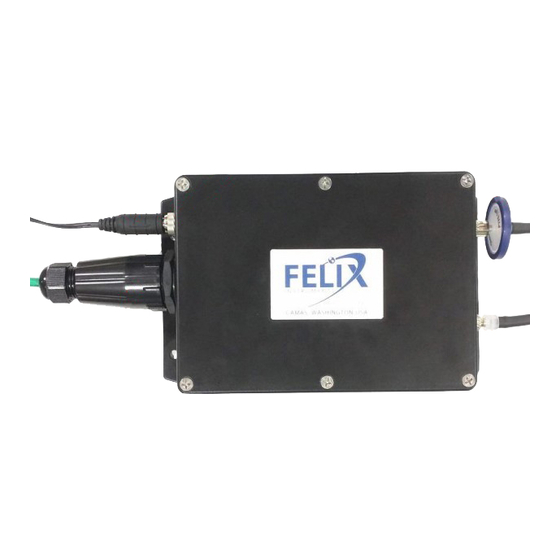
Instrument Overview 12V Power Input Mounting Holes* Gas Inlet Gas Outlet ModBus Communication Port *accepts M5 or #10 screw Cables and Tubes Installation Hydrophobic Filter Waterproof Power Plug Lock Ring Waterproof Cable Cap Luer-type Fitting IMPORTANT: USE ONLY SPECIFIED POWER PLUG AND CABLE CAP ... -
Page 6: Cables Assembly
Cables Assembly Lock Ring Plug handle 12VDC Waterproof Cap RJ45 Male Plug* *See Pin Description for correct wiring Connector Mating Parts (not supplied): Part number Description Manufacture 767KS12 Switchcraft DC Power Plug Sealed IP68 630125673867 Patch Cable Cap IP67 water and dust InstallerParts protection Page 5 of 18... -
Page 7: Principle Of Operation
F-901B SENSORS PUMP FILTER CHAMBER Figure 1 sampling cycle Cleaning Cycle: Air is circulated inside the F-901B through the sensor and filter chamber. Sensors are now isolated from the outside air. F-901B SENSORS PUMP FILTER CHAMBER Figure 2 cleaning cycle Operating modes ... -
Page 8: Modbus
RTU: The F901B sensor can be configurated to operating in RTU (RS485) mode by setting the MODBUS_MODE register and swapping the internal cables inside the sensor. See below for RTU specifications. Please contact Felix Instruments for details on how to configure sensor hardware in RTU mode. RTU RS485 Configuration... -
Page 9: Absolute Maximum Rating
Value Default address Baud Rate 19200 Data bits Parity Even Stop bits F-901B MODBUS Specifications Operates as a slave, half-duplex mode Modbus functions supported: 0x01 - Read Coils 0x03 - Read Holding Registers 0x04 - Read Input Registers... -
Page 10: Holding Registers
DEV_TYPE Default device type ID: 9011 FIRMWARE Firmware version Note: Above addresses are offsets. The function address for input register is [30001 + offset] Temperature and Humidity are measured at the sensor’s inlet and may not represent room condition or remoted/localized spots. -
Page 11: Coils
Backup calibration parameters before overwriting their values (performing a calibration) or update device firmware (all parameters will be erased). All F-901B comes with factory calibration using standard certified gases. Coils Mode: Read/Write, size: 1 bit... -
Page 12: Maintenance Of The F-901B
Power off device before you proceed Make sure you have sufficient ESD (electrostatic discharge) protection Follow the below steps carefully to ensure proper sensor installations Step 1: Remove the F-901B top cover Socket Sensor Connectors C2H4 sensor Filter Tube O2 sensor Step 4: Pull C2H4 sensor off socket. - Page 13 Step 5: remove short-cutting spring from new C2H4 sensor. (the spring keeps sensor from sensitivity/baseline drift during storage. Save it later for your old sensor) Step 6: remove old C2H4 sensor from connector, Plug in the new C2H4 sensor then push into socket push into socket Step 8: Apply force to both ends, gently Step 7: screw new O2 sensor into socket...
-
Page 14: Calibration
All units are shipped factory‐calibrated. Over time all sensors require recalibration to ensure accuracy. There are several options for calibration: You can ship your F-901B or individual sensor back to us for calibration You can order pre-calibrated sensors from us to replace your current sensors ... - Page 15 Calibration Procedures C2H4 Sensor Calibration Calibrating span on the C2H4 sensor should be performed in Trigger measurement mode. During this mode sensor only sampling for 35 seconds per sampling interval, therefore make sure calibration gas is applied properly during the sampling duration. Ignore initial measurements if necessary (flush measurements). A zero calibration is not necessary, however you can use Holding Register address 2 (C2H4_ZERO) to fine-tune the measurement baseline.
- Page 16 2. Apply fresh air (400ppm) at device inlet 3. Monitor sensor measurement at Input Register address 1 and wait until reading stabilized (~2 minutes) 4. Set ZERO_CO2 Coil (address 2) to request zero action (write 1 or TRUE value to register) 5.
- Page 17 1. Apply fresh air at device inlet 2. Monitor sensor measurement at Input Register address 2 and wait until reading stabilized (typically 2 to 3 measurement updates in Trigger mode or >=2 minutes in Continuous mode) 3. Set SPAN_209_O2 Coil (address 1) to request calibration action (write 1 or TRUE value to register) 4.
-
Page 18: Warranty Information
Material and equipment which is not manufactured by Felix Instruments are to be covered only by the warranty of its manufacturer. Felix Instruments will not be liable to the Buyer for loss, damage, or injury to persons or to property by the use of equipment manufactured by other companies. -
Page 19: Warranty Registration Card
Ave, Camas, WA 98607, USA Phone: (360) 833-8835 Fax: (360) 833-1914 e-mail: sales@felixinstruments.com Web: www.felixinstruments.com PRODUCT REGISTRATION CARD Please complete and return this form to Felix Instruments within 30 days to validate your Warranty on Parts & Labor. Registration Information: Your Name:____________________________________ Title:__________________...
Need help?
Do you have a question about the F-901B and is the answer not in the manual?
Questions and answers