Table of Contents
Advertisement
Advertisement
Table of Contents

Related Manuals for Portamatik TOP500


Summary of Contents for Portamatik TOP500
- Page 1 TOP500 v1.0 REV. 01/2019 USER’S AND INSTALLER’S MANUAL...
-
Page 2: Table Of Contents
(eg. charger, properly. The TOP500 operator is a product for residential USB cable, electronic material, controls, use, adaptable to all types of sliding gates. • If the operator is to be installed at a level higher than etc.) are susceptible to electric shock by... -
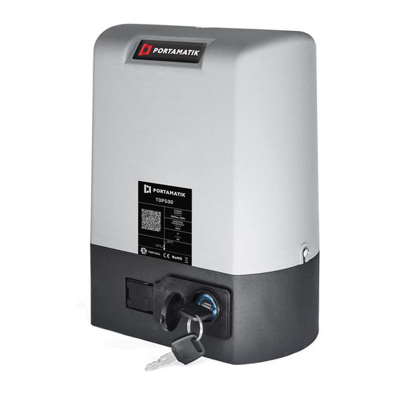
Page 3: Operator
During installation you will need to open the motor cover, to access various components on the inside. For this, loosen the 2 screws identified with (A) until the cover is free to be removed. The dimensions of the TOP500 operator are in milime- ters (mm) throughout the manual. -
Page 4: Instalation
INSTALLATION CREATE FOUNDATION EXISTING FOUNDATION If there is already a foundation at the installation site, proceed as follows: 1 • Place the plate on top of the concrete base. 2 • Mark the location to drill bushings. Mark the center of the oval holes in the plate. -
Page 5: Application Of Motor
APPLICATION OF MOTOR INSTALLATION OF NYLON GEAR RACK • Place the motor on the plate. • Tighten the 4 screws to the plate by the inside of the If you wish to install the Steel Rack, go to page 6 for the necessary instructions. engine. -
Page 6: Installation Of Nylon Gear Rack
1 • Place spacers in all rack holes to secure to the gate. You should place them in the center of the ovalized rack holes, so you can fine-tune them at the end of the installation if necessary. 2 • Position a piece of rack over the pinion and level it horizontally with a level. 3 •... -
Page 7: Installation Of Plates The Limit Switches
8 • Repeat the previous steps for each meter of rack until you reach the end. 9 • Test the gate movement manually with all racks installed and weld the remaining spacers. If there is any friction between the pinion and the rack, adjust the rack on the oval screws. INSTALLATION OF PLATES THE LIMIT SWITCHES •... -
Page 8: Maintenance
1 • Connect the power wires to the terminal, as shown. CHECK FRICTION BETWEEN RACK AND PINION 2 • Connect the operator wires to the terminal, inserting a capacitor into the opening and closing wires. • Make sure that the distance between rack and motor remains unchanged and that it engages the teeth of the 3 •... -
Page 9: Troubleshooting
TROUBLESHOOTING Anomaly Procedure Behavior Procedure II Discovering the origin of the problem • Motor • Make sure you • Still not working • Consult a qualified 1 • Open control board and check if 3 • Disconnect the motor from 4 •...
Need help?
Do you have a question about the TOP500 and is the answer not in the manual?
Questions and answers