
Subscribe to Our Youtube Channel
Related Manuals for SIGNALCORE SC5312A

Summary of Contents for SIGNALCORE SC5312A
- Page 1 SC5312A 400 MHz to 6 GHz IQ Demodulator PXI Express Interface Operating and Programming Manual © 2013-2020 SignalCore, Inc. support@signalcore.com...
- Page 2 LO Input Section IF Output Section SC5312A Programming Interface Device Drivers Using the Application Programming Interface (API) Setting the SC5312A: Writing to Configuration Registers Configuration Registers Initializing the Device Setting the System Active LED Setting the RF Frequency Setting RF Input RF Amplifiers...
- Page 3 Removing DC Offset in Differential Amplifiers Setting the Output Linearity of the IQ Demodulator Storing the Startup State Writing to the User EEPROM Querying the SC5312A: Writing to Request Registers Reading the Device Temperature Reading the Device Status Reading the User EEPROM...
-
Page 4: Warranty
Please contact SignalCore if errors are suspected. In no event shall SignalCore be liable for any damages arising out of or related to this document or the information contained in it. - Page 5 SignalCore, Incorporated uses a fully RoHS compliant manufacturing process for our products. Therefore, SignalCore hereby declares that its products do not contain restricted materials as defined by European Union directive 2002/95/EC (EU RoHS) in any amounts higher than limits stated in the directive. This statement is based on the assumption of reliable information and data provided by our component suppliers and may not have been independently verified through other means.
- Page 6 Warnings Regarding Use of SignalCore Products PRODUCTS FOR SALE BY SIGNALCORE, INCORPORATED ARE NOT DESIGNED WITH COMPONENTS NOR TESTED FOR A LEVEL OF RELIABILITY SUITABLE FOR USE IN OR IN CONNECTION WITH SURGICAL IMPLANTS OR AS CRITICAL COMPONENTS IN ANY LIFE SUPPORT SYSTEMS WHOSE FAILURE TO PERFORM CAN REASONABLY BE EXPECTED TO CAUSE SIGNIFICANT INJURY TO A HUMAN.
-
Page 7: Getting Started
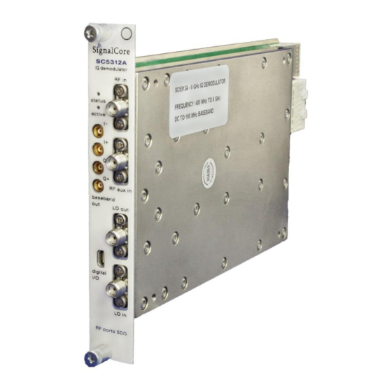
Setting Up and Configuring the SC5312A The SC5312A is a designed for use in a PXIe or PXIe hybrid chassis. Chassis manufacturers must provide at least the minimum required per-slot power dissipation cooling capability to be compliant with the PXIe specifications. - Page 8 The SC5312A is a PXIe-based IQ demodulator with all I/O connections and indicators located on the front face of the module as shown below. Each location is discussed in further detail below. Figure 1. Front panel view of the SC5312A.
- Page 9 All RF signal connections (ports) on the SC5312A are SMA-type. Exercise caution when fastening cables to the signal connections. Over-tightening any connection can cause permanent damage to the device. The condition of your system‘s signal connections can significantly affect measurement accuracy and repeatability.
- Page 10 50 Ω terminator. All baseband connectors are MCX female. Indicator LED The SC5312A provides visual indication of important modes. There is one LED indicator on the unit. Its behavior under different operating conditions is shown in Table 1. Table 1. LED indicator states.
-
Page 11: Operation
RF input levels. Figure 2 shows a simplified block diagram of the SC5312A, showing only the signal conditioning components critical for the following discussion. The following sections provide an in- depth discussion on how to optimize the converter for linearity and signal-to-noise dynamic range. - Page 12 Figure 2. Simplified block diagram of the SC5312A. SC5312A Operating & Programming Manual Rev 1.0.2...
- Page 13 6000 MHz LO Input Section The SC5312A requires an external RF signal as its “Local Oscillator” (LO) for the frequency conversion process. The external RF signal must be connected to the “LO in” port. The typical required input level is - 3 dBm to 3 dBm.
- Page 14 Generally, increasing the voltage results in higher the current consumption, and as a result the linearity improves. However slight adjustments to the voltage may improve the linearity further; this is dependent on the frequency and input power. SC5312A Operating & Programming Manual Rev 1.0.2...
-
Page 15: Device Drivers
N T E R F A C E Device Drivers The SC5312A is programmed by writing to its set of configuration registers, and its data is read back through its set of query registers. The user may program directly at register level or through the API library functions provided. -
Page 16: Configuration Registers
DAC value [7:0] DC_OFFSET_DAC 0x1A [15:8] DAC value [13:8] [23:16] Channel [7:0] DAC value [7:0] LINEARITY_DAC 0x1B [15:8] DAC value [13:8] STORE_STARTUP_STATE 0x1D [7:0] [7:0] Address [7:0] USER_EEPROM_WRITE 0x1F [15:8] Address [15:8] [23:16] Byte[7:0] SC5312A Operating & Programming Manual Rev 1.0.2... -
Page 17: Initializing The Device
RF_FILTER_SELECT (0x15) – There are 9 RF filters to select from to improve RF input second harmonic suppression. Bits [3:0] are used. Selecting the LO Filter LO_FILTER_SELECT (0x16) – There are 9 RF filters to select from to improve LO input second harmonic suppression. Bits [3:0] are used. SC5312A Operating & Programming Manual Rev 1.0.2... - Page 18 STORE_STARTUP_STATE (0x23) – Writing to this register will save the current device state as the new default power on (startup) state. All data written to this register will be ignored as only the write command is needed to initiate the save. SC5312A Operating & Programming Manual Rev 1.0.2...
- Page 19 (least significant) byte of the three bytes of data written to the register. The other two bytes contain the write address in the EEPROM. For example, to write user data 0x22 into address 0x1F00 requires writing 0x1F0022 to this register. SC5312A Operating & Programming Manual Rev 1.0.2...
- Page 20 It is not recommended to read the temperature too frequently, especially once the temperature of the SC5312A has stabilized. The temperature sensor is a serial device located inside the RF module. Therefore, like any other serial device, reading the temperature sensor requires a sending serial clock and data commands from the processor.
-
Page 21: Bit Description
C code would look something like the following: byte_value[4]; // read in earlier unsigned int uint32_value; float float32_value; count while (count < 4) { uint32_value = unit32_value | (byte_value[count] << (count*8)); count++; float32_value = *(float *)&uint32_value; SC5312A Operating & Programming Manual Rev 1.0.2... -
Page 22: E E P R O M M A P
Table 5. Calibration EEPROM map. EEPROM NUMBER OF ADDRESS TYPE DESCRIPTION DATA POINTS (HEX) Manufacturing Information Product serial number RF module number Product manufacture date Firmware revision Hardware revision Reserved Startup state Calibration temperature SC5312A Operating & Programming Manual Rev 1.0.2... - Page 23 CD:\Win\Driver\src directory to show how these functions are called and used. First, for C/C++, we define the constants and types which are contained in the C header file, sc5312a.h. These constants and types are useful not only as an include for developing user applications using the SC5312A API, but also for writing device drivers independent of those provided by SignalCore.
- Page 24 #define GET_TEMPERATURE 0x21 // get the internal temperature of the device #define USER_EEPROM_READ 0x23 // read a byte from the USER EEPROM #define CAL_EEPROM_READ 0x24 // read a byte from the calibration EEPROM SC5312A Operating & Programming Manual Rev 1.0.2...
-
Page 25: Type Definitions
Function Definitions and Usage The functions listed below are found in the sc5312a.dll dynamic linked library for the Windows operating system. These functions are also provided in the LabVIEW library, sc5312a.llb. The LabVIEW functions contain context-sensitive help (Ctrl-H) to assist with understanding the input and output parameters. - Page 26 == 0) //If no device are found deallocate memory and end the program for(i = 0; i<10;i++) free(visaResource[i]); free(visaResource); printf("No sc5312a devices detected. Press enter to continue.\n"); return //** sc5505a_OpenDevice, open device 0 status = sc5312a_OpenDevice(visaResource[0], &deviceHandle); // Free memory for(i = 0;...
- Page 27 Definition: sc5312a_SetRfAmplifier(unsigned int devHandle, bool amplifier, bool mode) Input: unsigned int deviceHandle (handle to the opened device) bool amplifier (0=AMP#1, 1=AMP#2) bool mode (disable/enable) Description: sc5312a_SetRfAmplifier enables or disables the RF amplifiers. SC5312A Operating & Programming Manual Rev 1.0.2...
- Page 28 Input: unsigned int deviceHandle (handle to the opened device) unsigned char filter (select the appropriate filter number 0-8) Description: sc5312a_SetLoFilter selects the active filter in the LO filter bank. SC5312A Operating & Programming Manual Rev 1.0.2...
- Page 29 (DAC value range 0 - 16383) Description: sc5312a_SetLinearityDac sets the current consumption of the IQ demodulator, which affects the linearity of the device. A DAC value of 3685 is recommended and is also the default factory setting. SC5312A Operating & Programming Manual Rev 1.0.2...
- Page 30 Code showing how to use this function: deviceStatus_t *devStatus; devStatus = (deviceStatus_t*)malloc(sizeof(deviceStatus_t)); status = sc5312a_GetDeviceStatus(devHandle, devStatus); if(devStatus->loEnable) printf("The LO Output Port is Enabled \n"); else printf("The LO Output Port is disabled \n"); free(deviceStatus); SC5312A Operating & Programming Manual Rev 1.0.2...
- Page 31 (handle to the opened device) unsigned int memAdd (EEPROM memory address) Output: unsigned char *byteData (the read back byte data) Description: sc5312a_ReadUserEeprom reads back a byte from a specific memory address of the user EEPROM. SC5312A Operating & Programming Manual Rev 1.0.2...
- Page 32 A I N T E N A N C E The SC5312A does not receive a factory calibration. The SC5312A is sold as a component and users will need to perform amplitude and IQ correction as part of their system, which may minimally include a digitizer, LO source, and the SC5312A.
Need help?
Do you have a question about the SC5312A and is the answer not in the manual?
Questions and answers