Table of Contents
Advertisement
Quick Links
Advertisement
Table of Contents

Subscribe to Our Youtube Channel
Related Manuals for Bay Tek Games GRIDIRON BLITZ


Summary of Contents for Bay Tek Games GRIDIRON BLITZ
-
Page 2: Factory Contact Information
FACTORY CONTACT INFORMATION BAY TEK GAMES INC. Pulaski Industrial Park 1077 East. Glenbrook Drive Pulaski, WI 54162 USA JOIN OUR SERVICE FIRST NETWORK! This free service is intended to keep you up to date on the latest game information, early notification of parts specials, pertinent technical bulletins, updates on retro fit parts, software upgrades, and much more. -
Page 3: Table Of Contents
WELCOME TO: Gridiron Blitz ........4... -
Page 4: Welcome To: Gridiron Blitz
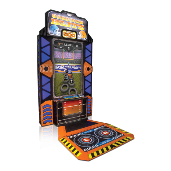
WELCOME TO: GRIDIRON BLITZ Get your knees up! Gridiron Blitz is a fast-paced, high-energy game that gets your players moving! With its interactive gameplay, great football theme and some slapstick humor thrown in, Grid- iron Blitz is sure to pump up the excitement at your location! Please take a moment to read through this manual and be sure to contact our factory if you have any questions, or would like some more information. -
Page 5: How To Play
HOW TO PLAY Step onto the pad and coin up. Run through the tires, jump the hurdles and avoid mascots and flying golf carts! Get through all three levels before time runs out to win tickets and get your time on the high score screen! Finish the third level in record time to win the jackpot! -
Page 6: Specifications
GAME SPECIFICATIONS POWER REQUIREMENTS WEIGHT INPUT VOLTAGE 100 to 120 220 to 240 NET WEIGHT 540 lbs. RANGE SHIP WEIGHT 600 lbs. INPUT FREQUENCY 50 HZ 60 HZ DIMENSIONS RANGE WIDTH 57” MAX START UP OPERATING DEPTH 84” CURRENT CURRENT HEIGHT 104”... -
Page 7: Quick Set Up Guide
QUICK SET UP Place the UNPLUGGED game near its final location. Cut the banding holding up the sensor pad and CAREFULLY lower it down to the floor. Buddy lift the marquee into place, plugging in the cable shown. Secure the marquee with 6 included silver panhead bolts and washers (hardware packet is in the cash- box). - Page 8 PROMO PLAY SETUP *NOT AVAILABLE ON ALL MACHINES* Move the game to desired promotional location; consider the game’s size and trip potential when choosing a location. Use the included straps to secure the pad in the upright position, and always use the buddy system when moving heavy objects.
-
Page 9: Main Menu Functions
MAIN MENU To access the menu, press the MENU button inside the front door of the cabinet. Scroll through the menus with the MENU button. Make your selections with the MENU SELECT button. MAIN MENU OPTIONS GAME VOLUME ATTRACT VOLUME JACKPOT VOLUME CLEAR TIX/CRED Press the menu button 3 times to clear tickets and credits owed... -
Page 10: Game Settings
LEVEL 3 MAX TIME 1 SEC 30 SEC DEFAULT: 10 *Each level must be completed within the set time to continue on to the next level GAMEPLAY OPTIONS ENTERTAINMENT DISABLED ENABLED** ONLY **Call Bay Tek Games’ Service Department to order entertainment only art. -
Page 11: Pay In/Out Menu
PAY IN/OUT MENU Progressive Cap: Progressive Inc: Increase: PAY IN/OUT OPTIONS CREDITS PER PLAY DEFAULT: 4 CREDITS (INCREMENTS OF 1) TRUE * CARD READER FALSE (CREDITS PER PLAY WILL DEFAULT TO 1) DIVIDE TICKETS BY 2 TRUE* FALSE JACKPOT START 1000 DEFAULT: 500 TICKETS (INCREMENTS OF 25) -
Page 12: Statistics
STATISTICS STATISTICS TOTAL GAMES Total number of games played since last Reset TOTAL TICKETS Total tickets dispensed since last Reset AVERAGE TICKETS Average tickets paid out per game since last Reset JACKPOTS WON Number of Jackpot wins recorded since last Reset HIGHEST JACKPOT Highest Jackpot value won AVG. -
Page 13: Diagnostics
DIAGNOSTICS DIAGNOSTICS READINGS Indicates which area of the sensor pad is being detected RIGHT - OTHER LEFT - OTHER LEFT - RIGHT OTHER (RIGHT FOOT (LEFT FOOT ONLY) (BOTH FEET) (NONE) ONLY) TEST TICKET Press menu button 3 times to test the ticket dispenser DISPENSE CHANGE Press menu button 3 times to test the colors of the side column lights... -
Page 14: Promotional Mode
PROMOTION MODE *NOT AVAILABLE ON ALL MACHINES* Some Gridiron Blitz games are equipped with software to support an upgraded card reader/dispenser unit to be used for promotional purposes. Turning on Promotion Mode enables free play via a button on the outside of the cabinet. -
Page 15: Wiring Diagrams
WIRING DIAGRAM AAMB2300 BOARD Outputs connector Lo Tix connector Inputs connector to to low ticket to LED switching hop pad interface switch Tix connector to ticket dispenser Comm connector to communication board Audio jack input DBA connector to bill acceptor To Count/Menu Coin connector to connector on... - Page 16 WIRING DIAGRAM MENU BUTTONS, COUNTERS, COIN MECHS, TICKET DISPENSERS Low Ticket Switch Wired Normally Open CE5516 To Ticket Dispenser Part # A5TD1 CE5516 12 Volt Power Enable Signal This connector is to be used for Card Swipe Systems CE5515 CE5515...
- Page 17 WIRING DIAGRAM POWER IN & 12 VOLTS ‐ + ‐ + STICK LIGHTS CE5521 ‐ + ‐ + ‐ + POWER TO PAD CE5520 Marquee LED lighting CE5512 To Power connector CE5507 on 2300 board SATA Hard POWER TO PAD BOARD CE5500 Drive A5HD1800 Power Supply AAMB9‐HD A5MO0060 AC Power to Bill Acceptor AC Power to Power Supply AC Power to Monitor...
- Page 18 WIRING DIAGRAM MOTHERBOARD COMMUNICATIONS, SPEAKERS, LED LIGHTING CE5523 CE5524 A5CORD21 TOWER LIGHTS LEFT AND RIGHT To Speaker connector on 2300 AACE2330 CE5501 Not Used CE5511 Not Used Speaker CE5501 CE5511 Speaker...
- Page 19 WIRING DIAGRAM SENSOR PAD CE5504 Emitter Boards - 2 Boards CE5512 To Cabinet Part # AACB2804 from power Two emitters per beam CE5505 CE5506 Pad area will detect blocked beams and register a hop Detector Boards - Two Boards Part # AACB2803 One detector per beam...
-
Page 20: Sensor Pad Diagnostics
SENSOR PAD DIAGNOSTICS The foot detection consists of 2 infrared emitter boards close to cabinet and 2 detector boards on the far edge of the hop pad. These boards create 24 beams of infrared light. The players feet interrupt these beams and the game interprets this as hops. The game is constantly reading these beams and re-calibrating the position of the player as they move across the pad There are multiple diagnostic tools that will help in troubleshooting a faulty hop pad:... - Page 21 SENSOR PAD DIAGNOSTICS Step 1: The most common issue is a dirty emitter or detector on the pad itself. If a beam is blocked the game will not register anything until the obstruction is removed. Solution: Clean the clear plexi that is protecting the emitters and detectors on both sides of pad.
- Page 22 SENSOR PAD DIAGNOSTICS Hop Pad Interface Board Troubleshooting Orange flashing LED health indicator on Pad Interface Board must be flashing. If LED is not flashing: - Check power in cable (# CE5512) from power supply to board. - Replace Pad Interface Board (part # AACB2805 LED indicators on Hop Pad Interface Board Left Middle...
-
Page 23: Troubleshooting Guide
TROUBLESHOOTING GUIDE Troubleshooting Strategy Use common sense and a systematic method of troubleshooting to determine the exact problem, probable cause and remedy. Use the process of elimination to find the faulty component. Always check for the simple and obvious causes first such as unplugged, loose or broken wires and bad sensors, bent, pinched, stuck or jammed components. - Page 24 TROUBLESHOOTING GUIDE PROBLEM PROBABLE CAUSE REMEDY Ensure game makes “doing” sound Check coin switches—both should be when coin switch is triggered. wired normally open. If one switch is “closed” the other will not work either. Verify communica�on Check wiring to 2300 board. (AACBL4A‐ between motherboard and 2300 board. DOOR, AACE5515) Game not coining up. Game set to large amount of credits per Refer to “Comm Error” troubleshoo�ng game. sec�on. Check Pay In/Out Menu. Ensure Credits per Game is set. Default = 4 12 Volt White LED’s Cabinet Ligh�ng does not work. These LED’s receive power directly from power supply There are 2 different types of cabinet Faulty cable. ligh�ng Refer to “Power In & 12 Volt Wiring Disconnected, loose or broken wires. Diagram” 12 Volt White LED’s & Individual LED strip out Iden�fy LED strip, check soldered wires, Colored LED’s that change color replace if needed. Colored LED’s Enter Diagnos�c menu and select These LED’s receive power from 2300 “Change Monitor Lights” ...
- Page 25 TROUBLESHOOTING GUIDE PROBLEM PROBABLE CAUSE REMEDY Tickets do not dispense or Wrong amount Opto Sensor on �cket dispenser dirty. Blow dust from sensor and clean with dispensed. Faulty �cket dispenser. isopropyl alcohol. Check for the correct amount of �ckets Notch on �ckets cut too shallow. Replace with working dispenser to isolate showing on Monitor the problem. (A5TD1) Faulty cable. Disconnected, loose or bro‐ ken wires. Flip �ckets and load upside‐down to have large cut notch toward up to sensor. Faulty 2300 Board. Check connectors from �cket dispensers to 2300 board. Check for con�nuity. Se�ngs in Menu are incorrect. Cable AACE5516 Replace 2300 board. (AAMB2300) Enter Pay In/Out Menu and check certain areas: Check Divide By 2 op�on Check Fixed Ticket Payout op�on Refer to “How to set �cket pa�erns” sec‐ �on Low Tickets message on monitor Tickets are empty in �cket tray Load �ckets into tray. Ensure �ckets hold down micro switch wire. Switch is part # The number of �ckets le� to dispense will Faulty cable. Disconnected, loose or AASW200 also show ...
- Page 26 TROUBLESHOOTING GUIDE Problem Probable Cause Remedy Verify meter does not click at end of This is done because Hop Star will not start a game un�l hop Game Meter does not work. game pad registers jumps. Game meter will click at end Disconnected, loose or broken wires. of game. Faulty counters. Check connec�ons and reseat Count/Menu on 2300 board. Cables # AACE5514 and AACO1000 Ensure correct number of Check �cket values, refer to Tickets not Ticket Meter does not work. �ckets are being dispensed. Dispensing troubleshoo�ng sec�on. Ticket meter will click as Disconnected, loose or broken wires. Check connec�ons and reseat Count/Menu on 2300 board. �ckets come out of game and Cables # AACE5514 and AACO1000 Faulty counters. notch is “seen” by dispenser. Replace counters. AACO1000 Disconnected, loose or broken wires. Check connec�ons from bu�on to 2300 board. Cables # AAPB2700 and AACE5514 Test bu�on; replace if needed. (AAPB2700) Menu Bu�ons do Faulty bu�on. ...
- Page 27 TROUBLESHOOTING GUIDE Problem Probable Cause Remedy Monitor not Monitor says Faulty power supply ‐ Check for 12 Volts and blinking green LED on SATA Drive Monitor “NO SIGNAL” for HDMI cable unplugged. Fan turning. Large power connector unplugged on motherboard. working. a�er power ‐up. Faulty or loose RAM Refer to Monitor/Motherboard Power Supply Diagnos�cs for further diagnos�c informa�on. Make sure video card is seated in motherboard all the way Power down, wait 10 sec‐ onds and power up again. Monitor has Power cable unplugged Ensure power is plugged into back of monitor, down to nothing at all on power strip. from monitor. power up. Push ON bu�on on monitor Faulty monitor. Replace monitor. (A5MO0060) Error on screen Monitor shows ASROCK SET‐ SATA Drive unplugged from board or faulty ...
- Page 28 TROUBLESHOOTING GUIDE PROBLEM PROBABLE CAUSE REMEDY Monitor shows “ASROCK SETUP UTILITY” SATA Drive not plugged in Small clip‐in hard drive is not being seen by computer. Bad SATA drive Push on spring clip and gently remove Power wire not plugged into SATA from motherboard. Re‐install and power on game. Try in different SATA slot on mother‐ board. Replace hard drive. (A5HD1800) Monitor shows “Sleep Mode” on screen. Power Supply or Motherboard not Check power supply voltage. Re‐Boot game to see if problem s�ll ex‐ communica�ng correctly with monitor. Replace power supply. (AAPS1008‐GB) ists. Ensure power supply connec�on is secure Power game down, wait 10 seconds, then to motherboard. power game ON to reset. Refer to Monitor/Motherboard Power Supply Diagnos�cs Replace motherboard. (AAMB9‐HD) Monitor shows “Kernel panic‐unable to Faulty or loose RAM Separate metal tabs on sides of RAM, it mount root” on screen. will ip up to remove. Re‐install and Re‐Boot game to see if problem s�ll exists. Power game down, wait 10 seconds, then power game ON to reset. Replace motherboard. (AAMB9‐HD) ...
-
Page 29: Error Messages
ERROR MESSAGES The 2300 board must communicate to the motherboard for the game to operate. “Power” solid ON Check green LED’s on Serial Interface board. “TX” & “RX” Should be blinking very fast If “Power” is not solid ON If “TX” & “RX” are not blinking very fast Power is supplied by 2300 board. -
Page 30: Power Supply Diagnostics
MONITOR/ POWER SUPPLY DIAGNOSTICS 1.) Verify AC power to game. 2.)Check power strip in front door. The rocker switch should be illuminated. 3.) Check connection to power supply. 4.) Ensure Power Supply switch is set to 115V (or 230V) (Some model power supplies may not have this) 5.) Ensure Power switch is on. -
Page 31: How To: Access/Remove Monitor
HOW TO: ACCESS & REMOVE MONITOR You only need to remove the monitor if it is bad!!!! Remove power to game. Remove carriage bolts around perimeter of monitor holding clear plexi and artwork on game. Carefully remove plexi and artwork from cabinet. Unscrew the 4 screws holding ... -
Page 32: Debit Card System Installation
DEBIT CARD SYSTEM INSTALLATION Remove black plastic cap from control panel of game, exposing the pre-cut holes for your card reader. Install card reader and follow next page for wiring instruction. - Page 33 DEBIT CARD SYSTEM SETUP The Gridiron Blitz game is pre-wired to accept Card Swipe systems from many manufactures. Please follow these instructions to make full use of Gridiron Blitz capabilities. Option #1: New card swipe systems may come with a standard 9 pin Molex connector.
-
Page 34: Circuit Board Pinout
AAMB2300 BOARD PINOUT GUIDE GRIDIRON BLITZ AAMB2300 I/O ALLOCATION POWER HEADER COIN PIN TYPE PURPOSE PIN# PIN TYPE PURPOSE PIN # +12V +12V COIN SIGNAL IN +5V ‐ ‐ +12V CREDIT INHIBIT/LOCKOUT INPUTS PIN TYPE PURPOSE PIN # +5V +12V MENU BUTTONS, MECH. COUNTERS Hop Pad Input 1 PIN TYPE PURPOSE PIN # Hop Pad Input 2 Hop Pad Input 3 MENU BUTTON 1 MENU BUTTON 2 GAME COUNTER OUTPUTS TICKETS COUNTER +12V PIN TYPE PURPOSE PIN #... -
Page 35: Maintenance Log
MAINTENANCE LOG If repairs are necessary, it is good practice to keep a log of repairs done and parts ordered. The chart below will assist you in tracking your game’s maintenance. DATE MAINTENANCE PERFORMED PARTS ORDERED INITIALS... -
Page 36: Technical Support
Bay Tek games. Many of our games share the same main-board electronics. This means you can buy one set of spare electronics to support many of your Bay Tek games. Spare boards allow you to get your game up and running the quickest and provide you a valuable troubleshooting option. Call our... -
Page 37: Warranty
WARRANTY Bay Tek Games warrants to the original purchaser that all game components will be free of defects in workmanship and materials for a period of 6 months from the date of purchase. If you fill out the registration card in the cashbox of the game, Bay Tek will add another 3 months to your warranty, free of charge.
Need help?
Do you have a question about the GRIDIRON BLITZ and is the answer not in the manual?
Questions and answers