Advertisement
Quick Links
95-10324_V2016-11-23 IF-812/IF-815
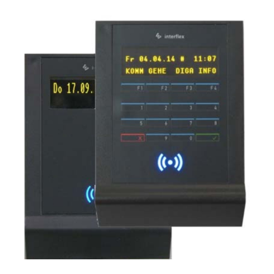
1 IF-812 or IF-815 Terminal (Slave)
Thank you for choosing an Interflex system. With an IF-812 or
IF-815 terminal (slave), you have purchased a reliable device
for capturing access data.
Furthermore, with an IF-815 terminal, you can also capture time
data and enter your PIN via a membrane keypad.
Scope of delivery:
IF-812 or IF-815 terminal (slave)
I/O controller board
Terminal board
Mortise lock
Material for wall mounting
Design frame optional
Please check the completeness and condition of the
shipment upon receipt.
2 Intended Use
Slave terminals of the IF-812/IF-815 series are devices for capturing access data as well as for writing to
RFID credentials. Furthermore, with an IF-815 terminal (slave), you can also capture time data. The device is
designed for indoor and outdoor use (see note). Any other use is not in accordance with the intended
purpose and is therefore not permitted.
3 Assembly and Installation
The following installation procedure has been proven and tested:
1. Install the cables.
2. Install the power supply.
3. Mount the IF-812/IF-815 housing. If the terminal is to be used for access control, an I/O controller board
must also be mounted in a secured area.
4. Set the address.
5. Close the housing.
6. Put the IF-812/IF-815 into operation.
Interflex Datensysteme GmbH
1/7
Advertisement

Subscribe to Our Youtube Channel
Related Manuals for Interflex IF-812

Summary of Contents for Interflex IF-812
- Page 1 1. Install the cables. 2. Install the power supply. 3. Mount the IF-812/IF-815 housing. If the terminal is to be used for access control, an I/O controller board must also be mounted in a secured area. 4. Set the address.
-
Page 2: Shielded Cables
The back panel of the housing (6) and the housing cover (8) are held together with internal catches and secured with a mortise lock (3). IF-812/IF-815 terminal (slave) Terminal strip board Tool for opening the housing of the IF-812/IF-815 Back panel of housing terminal, order no. 50-10137 Mortise lock... - Page 3 The back panel of the housing (1) must not warp when being screwed down. The IF-812/IF-815 terminal (slave) can be installed in dry or humid environments (IP43). Installation is performed on flat walls or pillars, e.g. next to doors, using the materials included in delivery. The I/O board is installed in a secured area, e.g.
- Page 4 IF-79 I/O BUS panel (max. 100 m). Connecting the BUS cable The IF-812/IF-815 terminal is connected to BUS1, BUS2 or BUS3 of a controller. Connecting the I/O controller board The I/O controller board is used for controlling electric actuators. If access control is not required, the I/O controller board can be omitted.
- Page 5 The I/O controller board allows for access control. The board can switch electric door openers up to max. 30 V 2 A via an NO or NC contact. It must be separated from the IF-812/IF-815 terminal and installed in a secured area, e.g. in a Hensel installation box (no. 78-700-0146) or a DIN appliance case.
-
Page 6: Circuit Examples
3.7.1 Circuit Examples Power supply (2) The IF-812/IF-815 terminal can be supplied with 12-24 V AC/DC via the I/O controller board. Connection of RS485 data cable (3) The RS485 data cable is connected to terminals 5, 6 and 7. The data cable may have a max. length of 1200 m. -
Page 7: Technical Specifications
IF-812: OLED 2 x 20 digit display IF-815: OLED 4 x 20 digit display Data entry Contrary to the IF-815 terminal (slave), the IF-812 terminal (slave) does not have a keypad. The IF-815 terminal (slave) has a membrane keypad with 4 programmable buttons as well as a numeric keypad.
Need help?
Do you have a question about the IF-812 and is the answer not in the manual?
Questions and answers