Advertisement
Quick Links
Installation Instruction – SW3-570
GPS[G]P & GPSK Series
A.
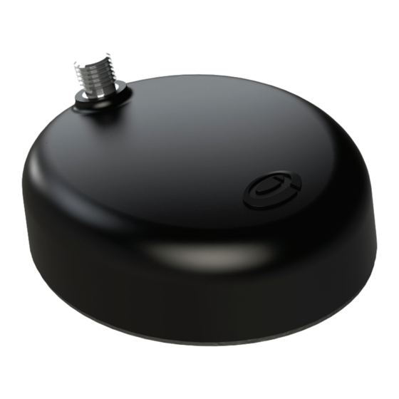
Introduction
The GPS(G)P antenna and GPSK combi antenna base incorporate
an active GNSS antenna module with 26dB gain LNA, which
supports GPS L1, GLONASS G1, Beidou and Galileo E1 services.
As supplied, it can be mounted on panels up to 6mm thick in a
single 15mm hole.
An extender kit is available as an option for use when fi tting to a
thick mounting panel.
Electrical Safety Note
This product contains an active GPS/GNSS antenna (part number SR8-HG26-04FJ). Rated voltage:
3-5VDC Rated current: 20mA maximum
The supply to this device must be provided with overcurrent protection of 1A maximum.
B.
Mounting requirements and selecting location
The antenna must be fi tted on a conductive ground plane of adequate size. For GPS only, the recommended size
is 10cm (3.9") diameter. For GPSK type, the target* ground plane size required will be dictated by the lowest
frequency used by the comms whip. This is based on a half wave diameter, and can be calculated by 150/Freq.
(MHz). Examples for common applications are shown below.
Diameter for:
150MHz = 1m (3.3'); 400MHz (TETRA) = 38cm (1.4'); 800MHz (GSM) = 19cm (7.5")
C.
Fitting the Antenna
Remove the protective backing from the underside of the antenna, feed the coaxial cable(s) through panel.
Position the antenna over the hole ensuring correct orientation and stick to panel by applying fi rm downward
pressure. Assemble the nut and washer from underside and tighten.
D.
Routing and terminating coaxial cable(s)
Connect the extension coaxial cables to the antenna and route them to the equipment, taking care to avoid
running the cables adjacent to any existing vehicle wiring or fouling any moving vehicle component. The cable(s)
must not be routed in front of any airbag device. Fit the correct coaxial connector or adaptor to the cable(s) as
required.
E.
Commission and test
Check GPS (GPS/GNSS) cable:
•
Check the GPS cable with DC to measure high resistance.
•
Connect the GPS cable to the GPS receiver and check for satellite acquisition.
When fi tting the antenna to a non-metallic panel, a ground plane plate of suitable
size should be fabricated and fi tted under the mounting panel; the securing washer
and nut must make a low resistance electrical contact with this plate (less than
0.2 ohm). Select a mounting location to ensure that there is adequate under panel
clearance and that there is no double skin panel or cross brace present. Measure
to check for central position if applicable.
*
Target refers to achieving the recommended size or as close as possible for optimum performance.
SW3-570 - Document Version 5.0
Advertisement

Related Manuals for Panorama Antennas GPSP Series


Summary of Contents for Panorama Antennas GPSP Series
- Page 1 Installation Instruction – SW3-570 GPS[G]P & GPSK Series SW3-570 - Document Version 5.0 Introduction The GPS(G)P antenna and GPSK combi antenna base incorporate an active GNSS antenna module with 26dB gain LNA, which supports GPS L1, GLONASS G1, Beidou and Galileo E1 services. As supplied, it can be mounted on panels up to 6mm thick in a single 15mm hole.
- Page 2 ..Cont’d. Check communications cable (GPSK only): • Earth continuity test: The connector body to the vehicle ground should measure <0.2Ω; • The connector body to the connector centre pin should measure open circuit. • Carry out a VSWR check, the VSWR should measure as detailed on the relevant datasheet. Connect the GPS and communications cables or stow the unused pigtails.