Table of Contents
Advertisement
SERVICE MANUAL
Ver. 1.1 2014.03
Note:
Be sure to keep your PC used for service and
checking of this unit always updated with the
latest version of your anti-virus software.
In case a virus affected unit was found during
service, contact your Service Headquarters.
Section for Speaker
Speakers
Super tweeter (Top): Approx. 19 mm (3/4 inches) diameter × 2 /
Super tweeter (Front): Approx. 19 mm (3/4 inches) diameter × 2 /
Midrange: Approx. 50 mm (2 inches) diameter × 2 /
Subwoofer: Approx. 94 mm (3 3/4 inches) diameter × 1
Section for Amplifier
POWER OUTPUT AND TOTAL HARMONIC DISTORTION:
Power Output (reference)
Super tweeter (Top): 2 W × 2 (at less than 10 % harmonic distortion,
20 kHz) / Super tweeter (Front): 25 W × 2 (at less than 10 % harmonic
distortion, 10 kHz) / Midrange: 25 W × 2 (at less than 10 % harmonic
distortion, 1 kHz) / Subwoofer: 25 W × 2 (at less than 10 % harmonic
distortion, 100 kHz)
Section for Network
Compatible standards
IEEE 802.11 b/g (WEP 64 bit, WEP 128 bit, WPA/WPA2-PSK (AES), WPA/
WPA2-PSK (TKIP))
Radio frequency (US, Canadian and Taiwan models)
2.412 GHz – 2.462 GHz (2.4 GHz ISM Band, 11 Channels) /
Channel 1 – Channel 11
Radio frequency (Except US, Canadian and Taiwan models)
2.412 GHz – 2.472 GHz (2.4 GHz ISM Band, 13 Channels) /
Channel 1 – Channel 13
Section for BLUETOOTH
Output
BLUETOOTH Specification Power Class 2
Maximum communication range
1
Line of sight Approx. 10 m (about 30 ft)*
Radio frequency
2.4 GHz band (2.4000 GHz – 2.4835 GHz)
Communication System
BLUETOOTH Specification Version 3.0
2
Compatible BLUETOOTH Profiles*
A2DP (Advanced Audio Distribution Profile) / AVRCP (Audio Video
Remote Control Profile)
3
Supported codec*
4
5
SBC (Subband Codec)*
/ AAC*
/ aptX
Transmission bandwidth (A2DP)
20 Hz – 20,000 Hz (with 44.1 kHz sampling)
1
*
The actual range will vary depending on factors such as obstacles
between devices, magnetic fields around a microwave oven, static
electricity, reception sensitivity, aerial's performance, operating
system, software application, etc.
2
*
BLUETOOTH standard profiles indicate the purpose of BLUETOOTH
communication between devices.
3
*
Codec: Audio signal compression and conversion format
4
*
Subband Codec
5
*
Advanced Audio Coding
9-893-947-02
Sony Corporation
2014C33-1
©
2014.03
Published by Sony Techno Create Corporation
SPECIFICATIONS
Section for USB port
USB A port (
A)
You can connect a compatible device such as an Android
smartphone, iPhone, etc., to this system, using a USB cable (not
supplied).
1
Supported format*
MP3 (MPEG 1 Audio Layer-3): 16 kbps – 320 kbps, CBR/VBR
AAC: 16 kbps – 320 kbps, CBR/VBR
WMA9 Standard: 16 kbps – 320 kbps, CBR/VBR
WAV: 32 kHz – 192 kHz, 16 bit PCM
32 kHz – 192 kHz, 24 bit PCM
FLAC: 8 kHz – 192 kHz, 16 bit FLAC
44.1 kHz – 192 kHz, 24 bit FLAC
Transfer speed
High-speed
Supported USB device
Mass Storage Class (MSC)
Maximum output current
2.1 A MAX
USB B port (
B)
You can connect a compatible device such as a computer, etc., to this
system, using a USB cable (not supplied).
1
Supported format*
PCM (44.1 k/48 k/88.2 k/96 k/176.4 k/192 kHz, 16/24/32 bit)
*
1
Compatibility with all encoding/writing software, recording
devices and recording media cannot be guaranteed.
SRS-X9
Canadian Model
AEP Model
Australian Model
Chinese Model
Singapore Model
Taiwan Model
Korean Model
Thai Model
General
AUDIO IN
ANALOG Φ 3.5 mm stereo mini jack
Network port
10BASE-T/100BASE-TX (Auto Polarity)
Power requirements
AREA
US, Canadian
Taiwan
Except US, Canadian, Taiwan
Power consumption
50 W
Power consumption (during standby mode)
Less than 0.5 W
Power consumption (during BLUETOOTH/network
standby mode)
Less than 3 W
Dimensions (w/h/d) (including projecting parts and
controls)
Approx. 430 mm × 133 mm × 125 mm (169.3 inches × 52.4 inches ×
49.2 inches)
Mass
Approx. 4.6 kg (162.3 oz)
Supplied accessories:
Remote control (RMT-CX9) (1) / AC power cord (1) (Except AEP and UK models) /
AC power cord (2) (AEP and UK models) / AAA size batteries for the remote
control (2) (for trial use) / Cleaning cloth (1) / Speaker grille detach tool (2) /
Start Guide "Enjoy Music over Your Wi-Fi Network" / Reference Guide /
Warranty card (US, Canadian, AEP, UK, Chinese, Korean and Thai models)
Design and specifications are subject to change without notice.
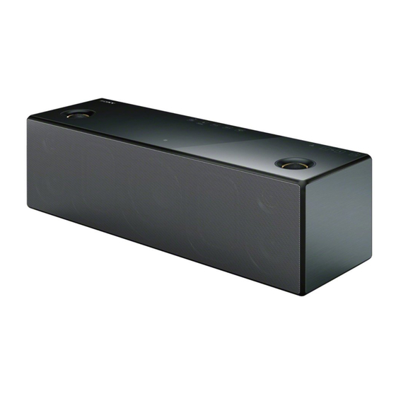
PERSONAL AUDIO SYSTEM
US Model
UK Model
Power requirements
120 V AC, 60Hz
110 V AC, 50Hz/60Hz
220 V – 240 V AC, 50Hz/60Hz
Advertisement
Table of Contents

Related Manuals for Sony SRS-X9


Summary of Contents for Sony SRS-X9
- Page 1 BLUETOOTH standard profiles indicate the purpose of BLUETOOTH communication between devices. Codec: Audio signal compression and conversion format Subband Codec Advanced Audio Coding PERSONAL AUDIO SYSTEM 9-893-947-02 Sony Corporation 2014C33-1 © 2014.03 Published by Sony Techno Create Corporation...
- Page 2 To Exposed Metal The BLUETOOTH® word mark and logos are owned by the Parts on Set Bluetooth SIG, Inc. and any use of such marks by Sony Corporation is under license. Other trademarks and trade names are those of their respective owners.
-
Page 3: Table Of Contents
SRS-X9 TABLE OF CONTENTS SERVICING NOTES DIAGRAMS ..........4-1. Block Diagram - MAIN Section - ........28 DISASSEMBLY 4-2. Block Diagram - AMP Section - ........29 4-3. Block Diagram 2-1. Disassembly Flow ............11 - PANEL, POWER SUPPLY Section - ......30 2-2. -
Page 4: Servicing Notes
SRS-X9 SECTION 1 SERVICING NOTES UNLEADED SOLDER NOTE OF REPAIRING THE BOARDS Boards requiring use of unleaded solder are printed with the lead- When boards other than the MAIN board installed by this unit are free mark (LF) indicating the solder contains no lead. - Page 5 SRS-X9 CHECKING METHOD OF NETWORK CONNECTION ABOUT THE DELETION METHOD OF USER REGIS- It is necessary to check the network connection, when replacing TRATION OF SEN SERVICE the WiFi module (Ref. No. WIFI1). Check the connection of wire- By checking device ID label, user registration of the internet video less LAN, according to the following method.
- Page 6 SRS-X9 Ver. 1.1 MODEL IDENTIFICATION Distinguish by model number label printed on the bottom side of a main unit. Note: The printed contents of following fi gure model number label may be different from the model number label of a main unit.
- Page 7 SRS-X9 • Please cut out along the dotted line and use it. Note of the MAC address change: Note of the MAC address change: The MAC address of this unit was changed along with this repair. The MAC address of this unit was changed along with this repair.
- Page 8 SRS-X9 MEMO...
- Page 9 SRS-X9 • Please cut out along the dotted line and use it. Request of the DLNA re-setup: Request of the DLNA re-setup: The DTCP-IP ID of this unit was changed along with this repair. The DTCP-IP ID of this unit was changed along with this repair.
- Page 10 SRS-X9 MEMO...
-
Page 11: Disassembly
SRS-X9 SECTION 2 DISASSEMBLY • This set can be disassembled in the order shown below. 2-1. DISASSEMBLY FLOW 2-2. GRILLE ASSY (Page 12) 2-3. BOTTOM PANEL ASSY 2-19. JACK BOARD (Page 12) (Page 24) 2-4. BAFFLE BLOCK 2-13. BLUETOOTH MODULE (BT1) 2-14. -
Page 12: Grille Assy
SRS-X9 Note: Follow the disassembly procedure in the numerical order given. 2-2. GRILLE ASSY The grille assy can be easily removed, if the speaker grille detach tool of the accessories of this unit is used. • 1 six magnets (grille) -
Page 13: Baffle Block
SRS-X9 2-4. BAFFLE BLOCK 2 S tight screw (PTTWH M3 1 six screws 3 ring (screw) (#3 HEX) (US, Canadian) Note: Please spread a sheet under a unit not to injure top panel. 1 six screws (#3 HEX) – Front bottom view –... -
Page 14: Speaker Wire (L-Ch, R-Ch)
SRS-X9 2-5. SPEAKER WIRE (L-ch, R-ch) ire etti ire etti [orange] binding band [black] [black] [white] [yellow] (taiton) [black] [red] binding band [black] [black] [yellow] [black] (taiton) [yellow] Note: In reassembling, use new binding band (taiton) to fasten the clamp same as before. -
Page 15: Led Board, Light Guide (C)
SRS-X9 2-6. LED BOARD, LIGHT GUIDE (C) ire etti [red] [black] filament tape (sub material) [white] REMOTE board LED board loudspeaker 2.2 cm (R-ch) [white] [black] 1 filament tape (sub material) 3 Remove the solder. [white] 3 Remove the solder. -
Page 16: Satellite Cabinet (L, R) Block
SRS-X9 2-7. SATELLITE CABINET (L, R) BLOCK satellite cabinet (R) block ditch satellite cabinet (L) block ditch loudspeaker 5.4 cm (R-ch) loudspeaker 5.4 cm (L-ch) 1 two tapping screws 1 two tapping screws (BV B3) 1 two tapping screws (BV B3) -
Page 17: Loudspeaker 2.2 Cm (L-Ch, R-Ch) (Sp2, Sp4)
SRS-X9 2-8. LOUDSPEAKER 2.2 cm (L-ch, R-ch) (SP2, SP4) 1 terminal (wide) (R-ch) 1 terminal (narrow) (R-ch) [brown] [black] 2 tapping screw (BV B3) 3 loudspeaker 2.2 cm 2 tapping screw (R-ch) (SP4) (BV B3) 1 terminal (narrow) (L-ch) [black]... -
Page 18: Loudspeaker 5.4 Cm (L-Ch, R-Ch) (Sp5, Sp6)
SRS-X9 2-9. LOUDSPEAKER 5.4 cm (L-ch, R-ch) (SP5, SP6) 35 mm cushion (wire) [yellow] [black] (wide) 75 mm cushion (wire) (narrow) [black] (narrow) [yellow] 75 mm loudspeaker 5.4 cm (wide) cushion (wire) (R-ch) (SP6) 50 mm 3 cushion (wire) 1 four tapping screws... -
Page 19: Plate (U) (Us, Canadian Models)
SRS-X9 Ver. 1.1 2-10. PLATE (U) (US, Canadian models) 1 two tapping screws (BV B3) 2 plate (U) – Baffle block bottom rear view – 2-11. LOUDSPEAKER (9.4 cm) (SP7) (Except US, Canadian) 1 tapping screw (BV B3) 1 tapping screw... -
Page 20: Loudspeaker (6.8 × 9.5 Cm) Passive (L-Ch, R-Ch) (Sp8, Sp9)
SRS-X9 Ver. 1.1 2-12. LOUDSPEAKER (6.8 × 9.5 cm) PASSIVE (L-ch, R-ch) (SP8, SP9) (Except US, Canadian) 1 three tapping screws (BV B3) 1 tapping screw (BV B3) 1 four tapping screws (BV B3) 2 loudspeaker (6.8 9.5 cm) passive (R-ch) (SP9) 2 loudspeaker (6.8... -
Page 21: Flexible Flat Cable (14 Core) (Ffc2)
SRS-X9 2-14. FLEXIBLE FLAT CABLE (14 CORE) (FFC2) filament tape ferrite core (sub material) filament tape filament tape (sub material) (sub material) flexible flat cable (14 core) (FFC2) filament tape (sub material) 6 connector (CN010) 5 Peel off the adhesive sheet (BT FFC). -
Page 22: 2-16. Main Board Block
SRS-X9 2-16. MAIN BOARD BLOCK 6 connector (CN100) 4 connector 8 MAIN board block (CN411) 7 connector (CN414) 5 connector (CN413) 3 antenna wire (CON2) 2 filament tape (sub material) 1 connector (CN508) CN100 filament tape (sub material) MAIN Board... -
Page 23: Power Unit (Pu1)
SRS-X9 2-18. POWER UNIT (PU1) 2 Remove the ferrite core from the clamp. 3 connector (CN101) 1 filament tape (sub material) clamp (L35) ferrite core (FC1) CN101 power case (U) filament tape (sub material) 7 power unit (PU1) 5 power case (U) block... -
Page 24: 2-19. Jack Board
SRS-X9 2-19. JACK BOARD ire etti 2 two screws CN004 CN008 CN006 (BTTP M2.6) 0 JACK board 1 screw 4 connector 2 three screws (CN006) (BTTP M2.6) 3 Remove the JACK 5 connector board in the direction (CN008) CN005 CN009 of the arrow. -
Page 25: Ac Inlet (2P) (Ac1)
SRS-X9 2-21. AC INLET (2P) (AC1) Sealing plate (AC) setting AC inlet wire setting AC inlet (2P) (AC1) long short ditch AC inlet (2P) (AC1) 3 two tapping screws (P B2.6) 5 AC inlet block 1 two tapping screws (P B2.6) -
Page 26: Test Mode
SRS-X9 SECTION 3 TEST MODE Buttons and indicator position: Button input settings under this mode of operation: [AUDIO IN]: System version display mode ([AUDIO IN] LED is blinking) [NETWORK]: WiFi module version display mode ([NETWORK] LED is blinking) PAIRING] and [VOL +] simultaneously: Bluetooth version... - Page 27 SRS-X9 Ver. 1.1 3. Destination display ALL LED LIGHTS ON MODE The check of the destination can be performed. Lighting of all the LED can be checked. Procedure: Procedure: 1. While entering the any fi rmware version display mode, press 1.
-
Page 28: Diagrams
SRS-X9 SECTION 4 DIAGRAMS 4-1. BLOCK DIAGRAM - MAIN Section - SDIN1, SDIN2, SDA1, SCL1, A/D CONVERTER SYSTEM CONTROLLER MCLK, LRCLK, SCLK, NMUTE, JACK BOARD (1/2) IC009 IC002 (1/2) NPDN, NBKND_ERR, NRESET, NCLIP, NOTW, NFAULT SDIN1 VINL LINE AMP 13 VINL... -
Page 29: Block Diagram - Amp Section
SRS-X9 4-2. BLOCK DIAGRAM - AMP Section - SDIN1, SDIN2, SDA1, SCL1, STREAM PROCESSOR DIGITAL POWER AMP MCLK, LRCLK, SCLK, NMUTE, IC503 IC507 NPDN, NBKND_ERR, NRESET, NCLIP, NOTW, NFAULT SDIN1 24 SDIN1 PWM_P_1 14 INPUT_C OUT_C L.P.F. SUPER 25 SDIN2... -
Page 30: Block Diagram - Panel, Power Supply Section
SRS-X9 4-3. BLOCK DIAGRAM - PANEL, POWER SUPPLY Section - SYSTEM CONTROLLER IC002 (2/2) KEY BOARD TOUCH-SDA 130 TOUCH-SDA2 TOUCH-SCL 129 TOUCH-SCL2 PIC-WRITE 120 PIC-WRITE +1.2V WIFI +1.2V REGULATOR RESET IC923 TOUCH-RESET SWITCH 41 TOUCH-NRESET PVDD Q102, 103 BCO-1.2V-ON +1.2V... - Page 31 SRS-X9 Ver. 1.1 THIS NOTE IS COMMON FOR PRINTED WIRING BOARDS AND SCHEMATIC DIAGRAMS. • Circuit Boards Location (In addition to this, the necessary note is printed in each block.) For Printed Wiring Boards. For Schematic Diagrams. Note: Note: • All capacitors are in μF unless otherwise noted. (p: pF) 50 •...
-
Page 32: Printed Wiring Boards - Main Section (1/2)
SRS-X9 Ver. 1.1 4-4. PRINTED WIRING BOARDS - MAIN Section (1/2) - • See page 31 for Circuit Boards Location. • : Uses unleaded solder. MAIN BOARD (COMPONENT SIDE) (CHASSIS) (CHASSIS) (CHASSIS) REMOTE Bluetooth JC506 C521 BOARD BOARD MODULE R590... -
Page 33: Printed Wiring Boards - Main Section (2/2)
SRS-X9 Ver. 1.1 4-5. PRINTED WIRING BOARDS - MAIN Section (2/2) - • See page 31 for Circuit Boards Location. • : Uses unleaded solder. POWER - AC IN MAIN BOARD UNIT (CONDUCTOR SIDE) IC001 CL554 C770 C707 C708 JL038... -
Page 34: Schematic Diagram - Main Section (1/6)
SRS-X9 4-6. SCHEMATIC DIAGRAM - MAIN Section (1/6) - • See page 40 for IC Block Diagrams. MAIN BOARD (1/6) VDD_BT C082 MAIN BOARD (6/6) R302 (Page 39) MAIN BOARD (2/6) CN010 (Page JL034 BT-RESET JL035 RESET_N JL036 3.3V JL037... -
Page 35: Schematic Diagram - Main Section (2/6)
SRS-X9 Ver. 1.1 4-7. SCHEMATIC DIAGRAM - MAIN Section (2/6) - • See page 40 for Waveforms. • See page 44 for IC Pin Function Description. MAIN BOARD (2/6) CN007 CL040 VCC3.3V CL041 TRST CL042 CL043 CL044 CL045 (NC) CL046... -
Page 36: Schematic Diagram - Main Section (3/6)
SRS-X9 4-8. SCHEMATIC DIAGRAM - MAIN Section (3/6) - • See page 40 for IC Block Diagrams. (ANTENNA) WIFI1 WiFi MAIN BOARD (3/6) MODULE R404 CN401 120P VDD_BC_1.2V FL402 FB402 VDD_BC_3.3V MAIN BOARD AOUT L+ FB413 VDD_SYS_3.3V (6/6) C403 PDOUT1/BCO_SPI_REQ PVDD 0.047... -
Page 37: Schematic Diagram - Main Section (4/6)
SRS-X9 4-9. SCHEMATIC DIAGRAM - MAIN Section (4/6) - • See page 40 for IC Block Diagrams. (SUBWOOFER) SUPER TWEETER SUPER TWEETER MIDRANGE (TOP) R-CH (FRONT) R-CH R-CH MIDRANGE SUPER TWEETER SUPER TWEETER L-CH (FRONT) L-CH (TOP) L-CH AC IN... -
Page 38: Schematic Diagram - Main Section (5/6)
SRS-X9 4-10. SCHEMATIC DIAGRAM - MAIN Section (5/6) - • See page 40 for IC Block Diagrams. MAIN (Page 37) BOARD (4/6) MAIN BOARD (5/6) R501 R502 R503 C520 C523 100k 100k 100k JC506 1000p 100V R538 R590 CL554 C518... -
Page 39: Schematic Diagram - Main Section (6/6)
SRS-X9 4-11. SCHEMATIC DIAGRAM - MAIN Section (6/6) - • See page 40 for Waveforms. • See page 40 for IC Block Diagrams. MAIN BOARD (6/6) IC923 IC B/D +1.2V REGULATOR IC923 C912 S-13A1A12-E6T1U3 L001 22uH FB904 FB902 BOOT VOUT VDD_BC_1.2V... - Page 40 SRS-X9 • Waveforms • IC Block Diagrams – MAIN Board – – MAIN Board – IC009 PCM1808PWR IC002 qf (AUDIO-MCLK) IC002 oa (AUDIO-X1) ANTIALIAS VINR LOW-PASS FILTER ANTIALIAS VINL LOW-PASS FILTER 3.8 Vp-p 3.8 Vp-p DELTA-SIGMA 40.6 ns 40.4 ns...
- Page 41 SRS-X9 IC503 TAS5538DGGR PWM_HPM_L 1 PWM_HPP_L 2 PWM_HPM_R 3 PWM_HPP_R 4 AVSS 5 PLL_FLTM 6 PLL_FLTP 7 VR_ANA 8 AVDD 9 ASEL_EMO2 10 MCLK 11 OSC_RES 12 POWER DVSS2_CORE 13 SUPPLY DVDD2_CORE 14 PWM_P_6 PWM_M_6 EMO1 15 PWM_P_5 RESET 16...
- Page 42 SRS-X9 IC504 – 507 TAS5624ADDVR GVDD_AB 1 BST_A BST_B VDD 2 OC_ADJ 3 RESET 4 OUT_A ANALOG PWM & TIMING GATE- LOOP FILTER CONTROL DRIVE INPUT_A 5 – OUT_A RECEIVER PVDD_AB PVDD_AB PVDD_AB INPUT_B 6 ANALOG PWM & TIMING GATE-...
- Page 43 SRS-X9 IC512, 919, 922 S-13A1A33-E6T1U3 IC918, 923 S-13A1A12-E6T1U3 VOUT 1 OVERCURRENT PROTECTION THERMAL SHUTDOWN ON/OFF CONTROL – REFERENCE VOLTAGE VSS 2 ON/OFF 3 INRUSH CURRENT LIMITING IC905, 906 TPS54331GDR 8 PH 7 GND BOOT MAXIMUM BOOT 1 UNDERVOLTAGE 6 COMP...
- Page 44 SRS-X9 • IC Pin Function Description MAIN BOARD IC002 R7S7200032CFP (SYSTEM CONTROLLER) Pin No. Pin Name Description Network/Bluetooth audio signal and clock signal selection signal output to the input select AUDIO-BT-BCO-SEL switch WiFi-M-CH-SEL Wi-Fi frequency setting terminal BCO-SPI-REQ Request signal input from the WiFi module...
- Page 45 SRS-X9 Pin No. Pin Name Description Not used VBUS-OE VBUS power on/off control signal output to the jack section “H”: power on Power supply terminal (+1.2V) NFC-RF-DET Interrupt detection signal input from the NFC module P-CONT-ON Power on/off control signal output terminal “H”: power on...
- Page 46 SRS-X9 Pin No. Pin Name Description Power supply terminal (+1.2V) PIC-WRITE Touch sensor IC write control signal output to the touch panel section Ground terminal LED-REACTION LED drive signal output terminal for reaction indicator LED “H”: LED on PVCC Power supply terminal (+3.3V)
-
Page 47: Exploded Views
SRS-X9 Ver. 1.1 SECTION 5 EXPLODED VIEWS Note: • -XX and -X mean standardized parts, so • Abbreviation The components identifi ed by mark 0 they may have some difference from the : Australian model or dotted line with mark 0 are critical for original one. -
Page 48: Super Tweeter (Front) Section
SRS-X9 5-2. SUPER TWEETER (FRONT) SECTION • Rear view not supplied baffle section not supplied not supplied not supplied not supplied not supplied not supplied not supplied not supplied Ref. No. Part No. Description Remark Ref. No. Part No. Description... -
Page 49: Baffle Section
SRS-X9 5-3. BAFFLE SECTION • Rear view SV-A (10 × 10) SV-A (10 × 10) not supplied (US, CND) not supplied Please cut out and use SERVICE CUSHION (EVA) (size 210 × 297 mm) for a specified size (unit: mm) when replacing it for new parts. -
Page 50: Main Board Section
SRS-X9 Ver. 1.1 5-4. MAIN BOARD SECTION FFC2 SV-B (20 × 50) WIFI1 not supplied supplied MAIN board not supplied supplied rear cabinet section not supplied not supplied supplied not supplied SV-A (25 × 100) SV-A (20 × 100) SV-A (25 ×... -
Page 51: Rear Cabinet Section
SRS-X9 Ver. 1.1 5-5. REAR CABINET SECTION Note: When replacing the Ref. No. 206 for new part, cut out and use it CAB1 for a specified size. 5 mm 5 mm SV-A (10 × 15) not supplied SV-A (10 × 15) -
Page 52: Electrical Parts List
SRS-X9 Ver. 1.1 SECTION 6 JACK MAIN ELECTRICAL PARTS LIST Note: • Due to standardization, replacements in • CAPACITORS When indicating parts by reference num- uF: μF the parts list may be different from the ber, please include the board name. - Page 53 SRS-X9 MAIN Ref. No. Part No. Description Remark Ref. No. Part No. Description Remark C081 1-100-158-91 CERAMIC CHIP 1000PF 100V C423 1-116-713-11 CERAMIC CHIP 22uF C082 1-118-347-11 CERAMIC CHIP 0.1uF C501 1-118-347-11 CERAMIC CHIP 0.1uF C083 1-118-347-11 CERAMIC CHIP 0.1uF...
- Page 54 SRS-X9 MAIN Ref. No. Part No. Description Remark Ref. No. Part No. Description Remark C586 1-100-436-91 CERAMIC CHIP 0.033uF C720 1-118-347-11 CERAMIC CHIP 0.1uF C587 1-100-436-91 CERAMIC CHIP 0.033uF C721 1-118-347-11 CERAMIC CHIP 0.1uF C588 1-100-436-91 CERAMIC CHIP 0.033uF C722 1-118-347-11 CERAMIC CHIP 0.1uF...
- Page 55 SRS-X9 MAIN Ref. No. Part No. Description Remark Ref. No. Part No. Description Remark C788 1-118-345-11 CERAMIC CHIP 0.01uF C947 1-118-290-11 CERAMIC CHIP 0.001uF C789 1-118-345-11 CERAMIC CHIP 0.01uF C948 1-118-290-11 CERAMIC CHIP 0.001uF C790 1-118-290-11 CERAMIC CHIP 0.001uF C791 1-118-345-11 CERAMIC CHIP 0.01uF...
- Page 56 SRS-X9 MAIN Ref. No. Part No. Description Remark Ref. No. Part No. Description Remark FB417 1-414-760-21 FERRITE, EMI (SMD) (1608) L402 1-457-223-11 COMMON MODE CHOKE COIL FB418 1-414-760-21 FERRITE, EMI (SMD) (1608) L502 1-460-659-11 COIL, CHOKE 10uH FB419 1-414-760-21 FERRITE, EMI (SMD) (1608)
- Page 57 SRS-X9 Ver. 1.1 MAIN Ref. No. Part No. Description Remark Ref. No. Part No. Description Remark R040 1-216-825-11 METAL CHIP 2.2K 1/10W R128 1-216-833-11 METAL CHIP 1/10W R041 1-216-809-11 METAL CHIP 1/10W R129 1-216-833-11 METAL CHIP 1/10W R042 1-216-809-11 METAL CHIP...
- Page 58 SRS-X9 MAIN REMOTE Ref. No. Part No. Description Remark Ref. No. Part No. Description Remark R210 1-218-990-81 SHORT CHIP R543 1-216-839-11 METAL CHIP 1/10W R211 1-216-864-11 SHORT CHIP R544 1-216-839-11 METAL CHIP 1/10W R212 1-216-821-11 METAL CHIP 1/10W R545 1-216-839-11...
- Page 59 SRS-X9 Ver. 1.1 Ref. No. Part No. Description Remark Ref. No. Part No. Description Remark MISCELLANEOUS ACCESSORIES ************** ************ 0 AC1 1-697-045-11 AC INLET (2P) 4-530-730-11 QUICK START GUIDE 1-490-558-81 BLUETOOTH MODULE (Start Guide “Enjoy Music over Your Wi-Fi Network”)
- Page 60 SRS-X9 Ver. 1.1 Ref. No. Part No. Description Remark 1-492-804-11 REMOTE COMMANDER (Remote control (RMT-CX9)) 0 502 1-846-425-42 CORD SET, POWER-SUPPLY (AC power cord) (US, CND) 0 503 1-846-429-62 CORD SET, POWER-SUPPLY (AC power cord (A)) (AEP, UK) 0 504...
- Page 61 SRS-X9 MEMO...
- Page 62 SRS-X9 REVISION HISTORY Checking the version allows you to jump to the revised page. Also, clicking the version at the top of the revised page allows you to jump to the next revised page. Ver. Date Description of Revision 2014.01 2014.03...
Need help?
Do you have a question about the SRS-X9 and is the answer not in the manual?
Questions and answers