
Subscribe to Our Youtube Channel
Related Manuals for S&T Kontron SDML-WLU0 Series


Summary of Contents for S&T Kontron SDML-WLU0 Series
- Page 1 USER GUIDE SDML-WLU0 Series Doc. User Guide, Rev. 1.0 Doc. ID: [To be Determined] www.kontron.com...
- Page 2 SDML-WLU0 Series - User Guide, Rev. 1.0 This page has been intentionally left blank www.kontron.com // 2...
- Page 3 SDML-WLU0 Series - User Guide, Rev. 1.0 SDML-WLU0 SERIES - USER GUIDE Disclaimer Kontron would like to point out that the information contained in this user guide may be subject to alteration, particularly as a result of the constant upgrading of Kontron products. This document does not entail any guarantee on the part of Kontron with respect to technical processes described in the user guide or any product characteristics set out in the user guide.
- Page 4 SDML-WLU0 Series - User Guide, Rev. 1.0 Intended Use THIS DEVICE AND ASSOCIATED SOFTWARE ARE NOT DESIGNED, MANUFACTURED OR INTENDED FOR USE OR RESALE FOR THE OPERATION OF NUCLEAR FACILITIES, THE NAVIGATION, CONTROL OR COMMUNICATION SYSTEMS FOR AIRCRAFT OR OTHER TRANSPORTATION, AIR TRAFFIC CONTROL, LIFE SUPPORT OR LIFE SUSTAINING APPLICATIONS, WEAPONS SYSTEMS, OR ANY OTHER APPLICATION IN A HAZARDOUS ENVIRONMENT, OR REQUIRING FAIL-SAFE PERFORMANCE, OR IN WHICH THE FAILURE OF PRODUCTS COULD LEAD DIRECTLY TO DEATH, PERSONAL INJURY, OR SEVERE PHYSICAL OR...
- Page 5 SDML-WLU0 Series - User Guide, Rev. 1.0 Revision History Revision Brief Description of Changes Date of Issue Author/ Editor Initial Issue 2021-Feb-08 Terms and Conditions Kontron warrants products in accordance with defined regional warranty periods. For more information about warranty compliance and conformity, and the warranty period in your region, visit http://www.kontron.com/terms- and-conditions.
-
Page 6: Symbols
SDML-WLU0 Series - User Guide, Rev. 1.0 Symbols The following symbols may be used in this user guide DANGER indicates a hazardous situation which, if not avoided, will result in death or serious injury. WARNING indicates a hazardous situation which, if not avoided, could result in death or serious injury. -
Page 7: For Your Safety
SDML-WLU0 Series - - User Guide, Rev. 1.0 For Your Safety Your new Kontron product was developed and tested carefully to provide all features necessary to ensure its compliance with electrical safety requirements. It was also designed for a long fault-free life. However, the life expectancy of your product can be drastically reduced by improper treatment during unpacking and installation. -
Page 8: Lithium Battery Precautions
SDML-WLU0 Series - User Guide, Rev. 1.0 Lithium Battery Precautions If your product is equipped with a lithium battery, take the following precautions when replacing the battery. Danger of explosion if the battery is replaced incorrectly. Replace only with same or equivalent battery type recommended by the manufacturer. ... -
Page 9: Table Of Contents
SDML-WLU0 Series - User Guide, Rev. 1.0 Table of Contents Symbols ..........................................6 For Your Safety ........................................7 High Voltage Safety Instructions .................................. 7 Special Handling and Unpacking Instruction ............................7 Lithium Battery Precautions ..................................8 General Instructions on Usage ..................................8 Quality and Environmental Management .............................. -
Page 10: List Of Tables
SDML-WLU0 Series - User Guide, Rev. 1.0 7.6. SPI 10-pin Header (CN4) ..................................42 7.7. M.2 Key B 2242 / 3042 / 2280 Slot (M2B1) ............................. 43 7.8. M.2 Key E 2230 / 3030 Slot (M2E1) ..............................46 7.9. M.2 Key M 2242 / 2280 Slot (M2M1) ..............................49 7.10. -
Page 11: List Of Figures
SDML-WLU0 Series - User Guide, Rev. 1.0 Table 26: Pin Assignment M2E1 .................................. 46 Table 27: Pin Assignment M2M1 ................................. 49 Table 28: Supplied fixing bolt extensions and fastening screws ..................... 51 Table 29: Installation configuration of M.2 Key B & M.2 Key E modules ..................52 Table 30: Installation configuration of M.2 Key M modules ...................... - Page 12 SDML-WLU0 Series - User Guide, Rev. 1.0 Figure 37: BIOS Advanced Menu - NVMe Configuration ........................68 Figure 38: BIOS Advanced Menu - SATA Configuration ........................69 Figure 39: BIOS Advanced Menu - USB Configuration ......................... 70 Figure 40: BIOS Advanced Menu - Trusted Computing ........................71 Figure 41: BIOS Advanced Menu - H/W Monitor ...........................
-
Page 13: 1/ Introduction
SDML-WLU0 Series - User Guide, Rev. 1.0 1/ Introduction This user guide describes the SDML-WLU0 Series module made by Kontron. This module will also be denoted SDML- WLU0 Series within this user guide. Use of this user guide implies a basic knowledge of PC-AT hardware and software. This user guide focuses on describing the SDML-WLU0 Series module's special features and is not intended to be a standard PC-AT textbook. -
Page 14: 2/ Installation Procedures
SDML-WLU0 Series - User Guide, Rev. 1.0 2/ Installation Procedures 2.1. Installing the Module ESD Sensitive Device! Electrostatic discharge (ESD) can damage equipment and impair electrical circuitry. Wear ESD-protective clothing and shoes Wear an ESD-preventive wrist strap attached to a good earth ground ... -
Page 15: Display Safety Standards
SDML-WLU0 Series - User Guide, Rev. 1.0 3. Connect interfaces Install M.2 SSD. Connect the power supply daughter card to the module. Insert all external cables for keyboard etc. A monitor must be connected in order to change BIOS settings. 4. - Page 16 SDML-WLU0 Series - User Guide, Rev. 1.0 Sustituya solamente por el mismo o tipo equivalente recomendado por el fabricante Disponga las baterías usadas según las instrucciones del fabricante ADVARSEL! Lithiumbatteri - - Eksplosionsfare ved fejlagtig håndtering. Udskiftning må kun ske med batteri af samme fabrikat og type ...
-
Page 17: 3/ System Specifications
SDML-WLU0 Series - User Guide, Rev. 1.0 3/ System Specifications 3.1. System Block Diagram Figure 1: System Block Diagram SDML-WLU0 Series www.kontron.com // 17... -
Page 18: Component Main Data
SDML-WLU0 Series - User Guide, Rev. 1.0 3.2. Component Main Data The table below summarizes the features of the SDML-WLU0 Series smart display module. Table 1: Component Main Data System Processor 8th Generation Intel® Core™ U-Series Processors Intel® Celeron® 4000 Series Processors Memory ... -
Page 19: Environmental Conditions
SDML-WLU0 Series - User Guide, Rev. 1.0 System H/W Monitor Voltages Temperatures Real Time Clock Processor integrated RTC vPro Supported for i7-8665UE & i5-8365UE TPM 2.0 (Infineon SLB 9665) System Control & Monitoring Button, Switch & ... - Page 20 SDML-WLU0 Series - User Guide, Rev. 1.0 CISPR 32: 2015 EN 61000-3-2: 2014 EN 61000-3-3: 2013 EN 55024: 2010 + A1: 2015 IEC 61000-4-2: 2008 IEC 61000-4-3: 2006 + A1: 2007 + A2: 2010 ...
-
Page 21: Processor Support
SDML-WLU0 Series - User Guide, Rev. 1.0 3.5. Processor Support The SDML-WLU0 Series is designed to support 8th Generation Intel® Core™ U-Series and Celeron® 4000 Series Processors. The BGA CPU is remounted from factory. Kontron has defined the module versions as listed in the following table. -
Page 22: On-Board Graphics Subsystem
SDML-WLU0 Series - User Guide, Rev. 1.0 SO-DIMM Type Module Name Memory Data Processor Resulting Peak Transfer Transfer (MT/s) System Bus Memory Clock Rate (MB/s) Frequency Frequency (MHz) (MHz) DDR4 2400 PC4-19200 2400 1200 19200 DDR4 2133 PC4-17000 2133 1067 17067 Memory modules have in general a much lower longevity than smart display modules, and therefore EOL of memory modules can be expected several times during lifetime of the smart display modules. - Page 23 SDML-WLU0 Series - User Guide, Rev. 1.0 www.kontron.com // 23...
-
Page 24: 4/ Connector Locations
SDML-WLU0 Series - User Guide, Rev. 1.0 4/ Connector Locations 4.1. Top Side Figure 2: Top Side Table 8: Jumper List Item Designation Description See Chapter MFG Mode Selection 7.12.1 USB Power Selection 7.12.2 M.2 Key B Lane 0 Selection 7.12.3 Flash Descriptor Security Override Selection 7.12.4... -
Page 25: Table 10: M.2 Fixing Bolt List
SDML-WLU0 Series - User Guide, Rev. 1.0 Item Designation Description See Chapter DIMM2 DDR4 Channel 1 SO-DIMM Slot M2B1 M.2 Key B 2242 / 3042 / 2280 Slot M2E1 M.2 Key E 2230 / 3030 Slot M2M1 M.2 Key M 2242 / 2280 Slot SDM Goldfinger Table 10: M.2 Fixing Bolt List Item... -
Page 26: Connector Panel Side
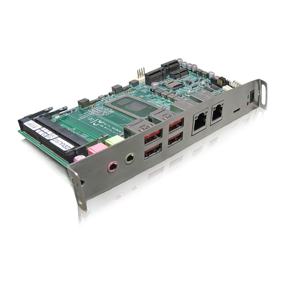
SDML-WLU0 Series - User Guide, Rev. 1.0 4.2. Connector Panel Side Figure 3: Connector Panel Side Table 11: Connector Panel Side Connector List Item Designation Description See Chapter CN10 GbE LAN1 RJ45 Connector CN11 GbE LAN2 RJ45 Connector CN12 USB 3.1 Port 1, 2 Type A Connector CN13 USB 3.1 Port 3, 4 Type A Connector CN14... -
Page 27: 5/ Connector Definitions
SDML-WLU0 Series - User Guide, Rev. 1.0 5/ Connector Definitions The following defined terms are used within this user guide to give more information concerning the pin assignment and to describe the connector's signals. Defined Term Description Shows the pin numbers in the connector Signal The abbreviated name of the signal at the current pin The notation "XX#"... -
Page 28: 6/ I/O-Area Connectors
SDML-WLU0 Series - User Guide, Rev. 1.0 6/ I/O-Area Connectors 6.1. Ethernet Connectors (CN10 & CN11) The SDML-WLU0 Series supports two channels of 10/100/1000 Mbit Ethernet, which are based Intel® I219-LM and Intel® I210-AT controller respectively. In order to achieve the specified performance of the Ethernet port, Category 5 twisted pair cables must be used with 10/100 MByte and Category 5E, 6 or 6E with 1 Gbit LAN networks. -
Page 29: Usb Connectors (I/O Area)
SDML-WLU0 Series - User Guide, Rev. 1.0 6.2. USB Connectors (I/O Area) The external I/O connector panel supports two dual USB 3.1 connectors. USB 3.1 ports are backward compatible with USB 3.0 and USB 2.0. Figure 5: USB 3.1 Connectors CN12 - Top & Bottom, CN13 - Top & Bottom Table 14: Pin Assignment USB 3.1 / USB 3.0 / USB 2.0 Connectors CN12 - Top &... -
Page 30: Figure 7: Usb 3.1 / Usb 3.0 High Speed Cable
SDML-WLU0 Series - User Guide, Rev. 1.0 Figure 7: USB 3.1 / USB 3.0 High Speed Cable Filler, optional UTP Signal Pair SDP Signal Pair Braid Jacket Power Ground SDP Signal Pair www.kontron.com // 30... -
Page 31: Micro Sd Card Holder (Cn14)
SDML-WLU0 Series - User Guide, Rev. 1.0 6.3. Micro SD Card Holder (CN14) The external I/O connector panel supports a push-push type micro SD card holder. Figure 8: Micro SD Card Holder CN14 Table 15: Pin Assignment CN14 Signal Description Note DAT2 Data line 2... -
Page 32: Optical S/Pdif Audio Port (Cn15)
SDML-WLU0 Series - User Guide, Rev. 1.0 6.4. Optical S/PDIF Audio Port (CN15) The external I/O connector panel supports an optical S/PDIF audio port to carry digital audio signals out to external speakers or deliver compressed AC3 signals to an external Dolby digital decoder. Figure 9: Optical S/PDIF Audio Port CN15 Table 16: Pin Assignment CN15 Signal... -
Page 33: Audio Jack Line-Out Connector (Cn16)
SDML-WLU0 Series - User Guide, Rev. 1.0 6.5. Audio Jack Line-out Connector (CN16) The external I/O connector panel supports a green audio jack line-out connector to connect the audio out signal to amplified speakers or headphones. Figure 10: Audio Jack Line-out Connector CN16 Table 17: Pin Assignment CN16 Signal Description... -
Page 34: Audio Jack Mic-In Connector (Cn17)
SDML-WLU0 Series - User Guide, Rev. 1.0 6.6. Audio Jack Mic-in Connector (CN17) The external I/O connector panel supports a pink audio jack mic-in connector to connect a microphone used for video conferencing, voice narrations, or simple audio recordings. Figure 11: Audio Jack Mic-in Connector CN17 Table 18: Pin Assignment CN17 Signal Description... -
Page 35: Power Led (Led1 Green)
SDML-WLU0 Series - User Guide, Rev. 1.0 6.7. Power LED (LED1 Green) The external I/O connector panel includes a power LED indicator. The power LED lights up green if the module powered on. 6.8. Storage LED (LED1 Red) The external I/O connector panel includes a storage LED indicator. The storage LED blinks red when data is being written into or read from the SSD which is installed in M.2 Key M socket. -
Page 36: 7/ Internal Connectors
SDML-WLU0 Series - User Guide, Rev. 1.0 7/ Internal Connectors 7.1. SDM Goldfinger (GF1) The SDML-WLU0 Series has an edge connector based on 98-pin PCIe x8 mechanical design with Intel® SDM compliant pin definition for connection to an Intel® SDM ready display. The SDM goldfinger supports power supply, DP, HDMI 2.0, USB 3.1, UART, PCIe x1, I2C, SPI and system management signals. - Page 37 SDML-WLU0 Series - User Guide, Rev. 1.0 Side B Side A Signal Description Signal Description USB_SSTX+ USB 3.1 Tx pair (+) PCIe_RX+ PCIe Rx pair (+) USB_SSTX- USB 3.1 Tx pair (-) PCIe_RX- PCIe RX pair (-) Ground Ground USB_SSRX+ USB 3.1 Rx pair (+) PCIe_CLK+ PCIe reference clock pair (+)
-
Page 38: Rtc Power Input Wafer (Cn18)
SDML-WLU0 Series - User Guide, Rev. 1.0 7.2. RTC Power Input Wafer (CN18) The 1x2-pin 1.25 mm pitch RTC power input wafer is intended to be connected to the battery. The battery provides power to the system clock to retain the time when power is turn off. Figure 13: RTC Power Input Wafer CN18 Table 20: Pin Assignment CN18 Signal... -
Page 39: Fan Wafer (Cn1)
SDML-WLU0 Series - User Guide, Rev. 1.0 7.3. Fan Wafer (CN1) The 1x4-pin 2.54 mm pitch fan wafer (CN1) is used for the connection of the fan for the processor. Figure 14: Fan Wafer CN1 Table 21: Pin Assignment CN1 Signal Description Note... -
Page 40: Usb Connectors (Internal) (Cn8)
SDML-WLU0 Series - User Guide, Rev. 1.0 7.4. USB Connectors (Internal) (CN8) The 10-pin 2.54 mm pitch USB port pin header CN8 supports two USB 2.0 ports. Figure 15: USB 2.0 Port 8, 9 Pin Header CN8 Table 22: Pin Assignment CN8 Signal Description Note... -
Page 41: P80 Header Lpc (Cn3)
SDML-WLU0 Series - User Guide, Rev. 1.0 7.5. P80 Header LPC (CN3) The header CN3 allows connection to a LPC Port 80 debug card to display the module’s debug information. Figure 16: P80 Header LPC CN3 Table 23: Pin Assignment CN3 Signal Description Note... -
Page 42: Spi 10-Pin Header (Cn4)
SDML-WLU0 Series - User Guide, Rev. 1.0 7.6. SPI 10-pin Header (CN4) The header CN4 is normally not used. It can be used to recover the BIOS SPI chip via an external SPI Flash IC programmer in case of BIOS corruption. Figure 17: SPI 10-pin Header CN4 Table 24: Pin Assignment CN4 Signal... -
Page 43: Key B 2242 / 3042 / 2280 Slot (M2B1)
SDML-WLU0 Series - User Guide, Rev. 1.0 7.7. M.2 Key B 2242 / 3042 / 2280 Slot (M2B1) The SDML-WLU0 Series supports M.2 modules in format 2242, 3042 or 2280 with Key B. The M.2 specification supports PCIe x1, USB 3.1 and SATA 3.0 signals as well as UIM signals connected to Micro SIM card holder CN2. The slot can be used to integrate WWAN communication or M.2 SSD to the module. - Page 44 SDML-WLU0 Series - User Guide, Rev. 1.0 Signal Description Note Ground USB3.0_RX- USB 3.1 receiver differential pair (-) UIM_RESET* SIM card reset USB3.0_RX+ USB 3.1 receiver differential pair (+) UIM_CLK* SIM card clock Ground UIM_DATA* SIM card data USB3.0_TX- USB 3.1 transmitter differential pair (-) UIM_PWR* SIM card power USB3.0_TX+...
- Page 45 SDML-WLU0 Series - User Guide, Rev. 1.0 Signal Description Note SIM_DETECT SIM card detect RESET# System reset SUSCLK 32.768 kHz clock supply input +3.3V 3.3 V power supply Ground +3.3V 3.3 V power supply Ground +3.3V 3.3 V power supply * These pins are connected to CN2 Micro SIM card holder directly.
-
Page 46: Key E 2230 / 3030 Slot (M2E1)
SDML-WLU0 Series - User Guide, Rev. 1.0 7.8. M.2 Key E 2230 / 3030 Slot (M2E1) The SDML-WLU0 Series supports M.2 modules in format 2230 or 3030 with Key E. The M.2 specification supports PCIe x1, USB 2.0 and CNVi signals. The slot can be used to integrate WLAN (Wi-Fi or CNVi Wi-Fi) and / or Bluetooth communication to the module. - Page 47 SDML-WLU0 Series - User Guide, Rev. 1.0 Key E CNVi Note Signal Description Signal Description UART_TX UART data output RGI_DT RGI bus Tx Ground Ground UART_CTS UART clear to send RGI_RSP RGI bus Rx PET0+ PCIe Lane 0 Tx pair (+) UART_RTS UART request to send BRI_DT...
- Page 48 SDML-WLU0 Series - User Guide, Rev. 1.0 Key E CNVi Note Signal Description Signal Description WT_D0N CNVio bus Tx Lane 0 (-) WT_D0P CNVio bus Tx Lane 0 (+) Ground Ground WT_CLKN CNVio bus Tx clock (-) +3.3V 3.3 V power supply +3.3V 3.3 V power supply WT_CLKP...
-
Page 49: Key M 2242 / 2280 Slot (M2M1)
SDML-WLU0 Series - User Guide, Rev. 1.0 7.9. M.2 Key M 2242 / 2280 Slot (M2M1) The SDML-WLU0 Series supports M.2 modules in format 2242 or 2280 with Key M. The M.2 specification supports PCIe x4 and SATA 3.0 signals. The slot can be used to integrate an M.2 PCIe x4 SSD (NVMe) or M.2 SATA SSD to the module. - Page 50 SDML-WLU0 Series - User Guide, Rev. 1.0 Signal Description Note Ground PERn1 PCIe Lane 1 receiver pair (-) PERp1 PCIe Lane 1 receiver pair (+) Ground PETn1 PCIe Lane 1 transmitter pair (-) PETp1 PCIe Lane 1 transmitter pair (+) DEVSLP Device sleep Ground...
-
Page 51: Table 28: Supplied Fixing Bolt Extensions And Fastening Screws
SDML-WLU0 Series - User Guide, Rev. 1.0 Signal Description Note SUSCLK 32.768 kHz clock supply input PEDET PCIe detect +3.3V 3.3 V power supply Ground +3.3V 3.3 V power supply Ground +3.3V 3.3 V power supply Ground In addition to fastening screws, the SDML-WLU0 Series is supplied with fixing bolt extensions for flexibly installing M.2 modules in different socket types and size formats. -
Page 52: Table 29: Installation Configuration Of M.2 Key B & M.2 Key E Modules
SDML-WLU0 Series - User Guide, Rev. 1.0 M.2 Fixing Bolt for Key M Type 2242 (see figure 2, pos. b) M.2 Fixing Bolt for Key M Type 2280 (see figure 2, pos. d) Table 29: Installation configuration of M.2 Key B & M.2 Key E modules Key E Type 2230 / 3030 Key B Type 2242 / 3042 Key B Type 2280... -
Page 53: Micro Sim Card Holder For M.2 Key B (Cn2)
SDML-WLU0 Series - User Guide, Rev. 1.0 7.10. Micro SIM Card Holder for M.2 Key B (CN2) The Micro SIM card holder CN2 is intended to accommodate an Micro SIM card and connected to UIM signals on the M.2 Key B slot (M2B1). Figure 22: Micro SIM Card Holder CN2 Table 31: Pin Assignment CN2 Signal... -
Page 54: Key B / M.2 Key E Activity Indicator Header (Cn9 & Cn5)
SDML-WLU0 Series - User Guide, Rev. 1.0 7.11. M.2 Key B / M.2 Key E Activity Indicator Header (CN9 & CN5) The header CN9 is intended to connect M.2 Key B activity LED cable. The pin header CN5 is intended to connect M.2 Key E activity LED cable. Figure 23: M.2 Key B Activity Indicator Header CN9 Table 32: Pin Assignment CN9 Signal... -
Page 55: Switches And Jumpers
SDML-WLU0 Series - User Guide, Rev. 1.0 7.12. Switches and Jumpers The product has several jumpers which must be properly configured to ensure correct operation. Figure 25: Jumper Connector For a three-pin jumper (see Figure 25), the jumper setting is designated ‘‘1-2’’ when the jumper connects pins 1 and 2. The jumper setting is designated ‘‘2-3’’... -
Page 56: Usb Power Selection (Jp3)
SDML-WLU0 Series - User Guide, Rev. 1.0 7.12.2. USB Power Selection (JP3) The 2.0 mm pitch "USB Power Selection" jumper (JP3) can be used to determine whether the USB ports are powered in the S4 / S5 state. Figure 27: USB Power Selection JP3 Table 35: Pin Assignment JP3 Jumper 1 Position Description... -
Page 57: Flash Descriptor Security Override Selection (Jp5)
SDML-WLU0 Series - User Guide, Rev. 1.0 7.12.4. Flash Descriptor Security Override Selection (JP5) The 2.0 mm pitch "Flash Descriptor Security Override Selection" jumper (JP5) can be used to specify whether to override the flash descriptor. Figure 29: Flash Descriptor Security Override Selection JP5 Table 37: Pin Assignment JP5 Jumper 1 Position Description... -
Page 58: Clear Cmos Selection (Jp7)
SDML-WLU0 Series - User Guide, Rev. 1.0 7.12.6. Clear CMOS Selection (JP7) The 2.0 mm pitch "Clear COMS Selection" jumper (JP7) can be used to reset the Real Time Clock (RTC) and drain RTC well. The jumper has one position: Pin 1-2 mounted (default position) and Pin 2-3 mounted. More information on setting the "Clear CMOS Selection"... -
Page 59: 8/ Bios
SDML-WLU0 Series - User Guide, Rev. 1.0 8/ BIOS 8.1. Starting the uEFI BIOS The SDML-WLU0 Series is provided with a Kontron-customized, pre-installed and configured version of AMI Aptio® V uEFI BIOS. AMI BIOS firmware is based on the Unified Extensible Firmware Interface (UEFI) specification and the Intel® Platform Innovation Framework for EFI. -
Page 60: Starting The Uefi Bios
SDML-WLU0 Series - User Guide, Rev. 1.0 8.2. Starting the uEFI BIOS The Setup utility features shows six menus in the selection bar at the top of the screen: Main Advanced Power Boot Security Save &... -
Page 61: Figure 32: Bios Main Menu Screen System Data And Time
SDML-WLU0 Series - User Guide, Rev. 1.0 Figure 32: BIOS Main Menu Screen System Data and Time BIOS SETUP UTILITY Main Advanced Power Boot Security Save & Exit Oem Board ID Product Information Product Name SDML-WLU BIOS Version WHLUSL.007 (x64) BIOS Build Date 10/29/2020 ME Firmware SKU... -
Page 62: Figure 33: Bios Main Menu - Main
SDML-WLU0 Series - User Guide, Rev. 1.0 Figure 33: BIOS Main Menu - Main BIOS SETUP UTILITY Main Advanced Power Boot Security Save & Exit BIOS Information BIOS Vendor American Megatrends Core Version 5.13 Compliancy UEFI 2.7; PI 1.6 Project Version 1AUOK 0.54 x64 Build Date and Time 10/29/2020 16:15:57... - Page 63 SDML-WLU0 Series - User Guide, Rev. 1.0 BIOS SETUP UTILITY Main Advanced Power Boot Security Save & Exit Chipset Base Revision Chipset OEM Revision Package Not Implemented Yet TXT Capability of Platform / PCH Unsupported Production Type Production Dual Output Fast Read support Not supported Read ID / Status Clock Freq 30 MHz...
-
Page 64: Advanced Setup Menu
SDML-WLU0 Series - User Guide, Rev. 1.0 8.2.2. Advanced Setup Menu The Advanced setup menu provides sub-screens and functions for advanced configurations. The following sub- screen functions are included in the menu: LAN, Audio & SD Card Configuration Display Configuration ... -
Page 65: Figure 34: Bios Advanced Menu
SDML-WLU0 Series - User Guide, Rev. 1.0 Figure 34: BIOS Advanced Menu BIOS SETUP UTILITY Main Advanced Power Boot Security Save & Exit Onboard LAN1 Controller [Enabled] Onboard LAN2 Controller [Enabled] Load I219 UNDI Driver [Disabled] Load I210 UNDI Driver [Disabled] Audio Controller [Enabled]... -
Page 66: Figure 35: Bios Advanced Menu - Display Configuration
SDML-WLU0 Series - User Guide, Rev. 1.0 Figure 35: BIOS Advanced Menu - Display Configuration BIOS SETUP UTILITY Main Advanced Power Boot Security Save & Exit Display Configuration Primary Display [IGFX] → ←: Select Screen Internal Graphics* [Enabled] ↑ ↓: Select Item Aperture Size [256MB] Enter: Select... -
Page 67: Figure 36: Bios Advanced Menu - Cpu Chipset Configuration
SDML-WLU0 Series - User Guide, Rev. 1.0 Figure 36: BIOS Advanced Menu - CPU Chipset Configuration BIOS SETUP UTILITY Main Advanced Power Boot Security Save & Exit CPU Chipset Configuration EIST [Disabled] → ←: Select Screen Turbo Mode* [Disabled] ↑ ↓: Select Item Hyper-Threading [Disabled] Enter: Select... -
Page 68: Figure 37: Bios Advanced Menu - Nvme Configuration
SDML-WLU0 Series - User Guide, Rev. 1.0 Figure 37: BIOS Advanced Menu - NVMe Configuration BIOS SETUP UTILITY Main Advanced Power Boot Security Save & Exit NVMe Configuration No NVMe Device Found → ←: Select Screen ↑ ↓: Select Item Enter: Select +/-: Change Opt. -
Page 69: Figure 38: Bios Advanced Menu - Sata Configuration
SDML-WLU0 Series - User Guide, Rev. 1.0 Figure 38: BIOS Advanced Menu - SATA Configuration BIOS SETUP UTILITY Main Advanced Power Boot Security Save & Exit SATA Configuration SATA Controller(s) [Enabled] → ←: Select Screen SATA Mode Selection* [AHCI] ↑ ↓: Select Item Enter: Select +/-: Change Opt. -
Page 70: Figure 39: Bios Advanced Menu - Usb Configuration
SDML-WLU0 Series - User Guide, Rev. 1.0 Figure 39: BIOS Advanced Menu - USB Configuration BIOS SETUP UTILITY Main Advanced Power Boot Security Save & Exit USB Configuration USB Devices: → ←: Select Screen 1 Keyboard ↑ ↓: Select Item Enter: Select Legacy USB Support [Enabled]... -
Page 71: Figure 40: Bios Advanced Menu - Trusted Computing
SDML-WLU0 Series - User Guide, Rev. 1.0 Figure 40: BIOS Advanced Menu - Trusted Computing BIOS SETUP UTILITY Main Advanced Power Boot Security Save & Exit Configuration Security Device Support [Disabled] No Security Device Found → ←: Select Screen ↑ ↓: Select Item Enter: Select +/-: Change Opt. -
Page 72: Figure 41: Bios Advanced Menu - H/W Monitor
SDML-WLU0 Series - User Guide, Rev. 1.0 Figure 41: BIOS Advanced Menu - H/W Monitor BIOS SETUP UTILITY Main Advanced Power Boot Security Save & Exit PC Health Status > Smart FAN Configuration CPU Temperature : +35 C Memory Temperature : +32 C System Temperature : +29 C... - Page 73 SDML-WLU0 Series - User Guide, Rev. 1.0 BIOS SETUP UTILITY Main Advanced Power Boot Security Save & Exit 2nd FAN Speed F1: General Help 3rd Boundary Temperature F2: Previous Values 3rd FAN Speed F3: Optimized Defaults 4th Boundary Temperature F4: Save & Exit 4th FAN Speed ESC: Exit Version 2.20.1275.
-
Page 74: Figure 43: Bios Advanced Menu - Network Stack
SDML-WLU0 Series - User Guide, Rev. 1.0 Figure 43: BIOS Advanced Menu - Network Stack BIOS SETUP UTILITY Main Advanced Power Boot Security Save & Exit Network Stack [Disabled] Ipv4 PXE Support* [Disabled] Ipv4 HTTP Support* [Disabled] → ←: Select Screen Ipv6 PXE Support* [Disabled] ↑... -
Page 75: Power Setup Menu
SDML-WLU0 Series - User Guide, Rev. 1.0 8.2.3. Power Setup Menu The Power setup menu provides functions and a sub-screen for power configurations. The following sub-screen function is included in the menu: WatchDog Timer Configuration Figure 44: BIOS Power Setup Menu BIOS SETUP UTILITY Main Advanced... -
Page 76: Figure 45: Bios Power Setup Menu - Watchdog Timer Configuration
SDML-WLU0 Series - User Guide, Rev. 1.0 Feature Option Description Alarm on your system on a special day of the month. Date(Days)Alarm Value Input 0 - - 31, 0 stands for every day. Time(hh)Alarm Value Input 0 - - 23 Time(mm)Alarm Value Input 0 - - 59... -
Page 77: Boot Setup Menu
SDML-WLU0 Series - User Guide, Rev. 1.0 8.2.4. Boot Setup Menu The boot setup menu lists the for boot device priority order, that is generated dynamically. Figure 46: BIOS Boot Setup Menu BIOS SETUP UTILITY Main Advanced Power Boot Security Save &... -
Page 78: Security Setup Menu
SDML-WLU0 Series - User Guide, Rev. 1.0 8.2.5. Security Setup Menu The Security setup menu provides information about the passwords and functions for specifying the security settings. The passwords are case-sensitive. The SDML-WLU0 Series provides no factory-set passwords. If there is already a password installed, the system asks for this first. To clear a password, simply enter nothing and acknowledge by pressing <RETURN>. -
Page 79: Figure 48: Bios Security Setup Menu - - Secure Boot
SDML-WLU0 Series - User Guide, Rev. 1.0 Figure 48: BIOS Security Setup Menu -- - Secure Boot BIOS SETUP UTILITY Main Advanced Power Boot Security Save & Exit System Mode Setup Secure Boot [Disabled] → ←: Select Screen Not Active ↑... -
Page 80: Figure 49: Bios Security Setup Menu - - Secure Boot - - Key Management
SDML-WLU0 Series - User Guide, Rev. 1.0 Figure 49: BIOS Security Setup Menu -- - Secure Boot -- - Key Management BIOS SETUP UTILITY Main Advanced Power Boot Security Save & Exit Vendor Keys Valid Factory Key Provision [Disabled] > Restore Factory Keys >... - Page 81 SDML-WLU0 Series - User Guide, Rev. 1.0 Feature Option Description (c) EFI_CERT_RSA2048 (bin) Authorized [Details], [Export], Signatures [Update], [Append], (d) EFI_CERT_SHAXXX [Delete] 2. Authenticated UEFI Variable 3. EFI PE / COFF Image (SHA256) Forbidden Signatures [Details], [Export], [Update], [Append], Key Source: Factory, External, Mixed [Delete] Authorized [Update], [Append]...
- Page 82 SDML-WLU0 Series - User Guide, Rev. 1.0 8.2.5.1. Remember the password It is highly recommended to keep a record of all passwords in a safe place. Forgotten passwords results in being locked out of the system. If the system cannot be booted because the User Password or the Supervisor Password are not know, contact Kontron Support for further assistance.
-
Page 83: Save & Exit Setup Menu
SDML-WLU0 Series - User Guide, Rev. 1.0 8.2.6. Save & Exit Setup Menu The exit setup menu provides functions for handling changes made to the UEFI BIOS settings and the exiting of the setup program. Figure 50: BIOS Save & Exit Setup Menu BIOS SETUP UTILITY Main Advanced... -
Page 84: Appendix A: List Of Acronyms
SDML-WLU0 Series - User Guide, Rev. 1.0 Appendix A: List of Acronyms The following table does not contain the complete acronyms used in signal names, signal type definitions or similar. A description of the signals is included in the I/O Connector and Internal connector chapters within this user guide. -
Page 85: About Kontron
SDML-WLU0 Series - - User Guide, Rev. 1.0 About Kontron Kontron is a global leader in Embedded Computing Technology (ECT). As a part of technology group S&T, Kontron offers a combined portfolio of secure hardware, middleware and services for Internet of Things (IoT) and Industry 4.0 applications.
Need help?
Do you have a question about the Kontron SDML-WLU0 Series and is the answer not in the manual?
Questions and answers