
Subscribe to Our Youtube Channel
Related Manuals for S&T kontron QSEVEN-Q7AL 2 Series


Summary of Contents for S&T kontron QSEVEN-Q7AL 2 Series
- Page 1 USER GUIDE QSEVEN-Q7ALx2 Doc. Preliminary User Guide, Rev. 0.7 Doc. ID: 1067-2270 www.kontron.com // 1...
- Page 2 QSEVEN-Q7ALx2 - Preliminary User Guide, Rev. 0.7 This page has been intentionally left blank www.kontron.com // 2...
- Page 3 QSEVEN-Q7ALx2 - Preliminary User Guide, Rev. 0.7 QSEVEN-Q7ALX2 - USER GUIDE Disclaimer Kontron would like to point out that the information contained in this user guide may be subject to alteration, particularly as a result of the constant upgrading of Kontron products. This document does not entail any guarantee on the part of Kontron with respect to technical processes described in the user guide or any product characteristics set out in the user guide.
- Page 4 QSEVEN-Q7ALx2 - Preliminary User Guide, Rev. 0.7 Intended Use THIS DEVICE AND ASSOCIATED SOFTWARE ARE NOT DESIGNED, MANUFACTURED OR INTENDED FOR USE OR RESALE FOR THE OPERATION OF NUCLEAR FACILITIES, THE NAVIGATION, CONTROL OR COMMUNICATION SYSTEMS FOR AIRCRAFT OR OTHER TRANSPORTATION, AIR TRAFFIC CONTROL, LIFE SUPPORT OR LIFE SUSTAINING APPLICATIONS, WEAPONS SYSTEMS, OR ANY OTHER APPLICATION IN A HAZARDOUS ENVIRONMENT, OR REQUIRING FAIL-SAFE PERFORMANCE, OR IN WHICH THE FAILURE OF PRODUCTS COULD LEAD DIRECTLY TO DEATH, PERSONAL INJURY, OR SEVERE PHYSICAL OR...
- Page 5 QSEVEN-Q7ALx2 - Preliminary User Guide, Rev. 0.7 Revision History Revision Brief Description of Changes Date of Issue Author Initial hardware info 2020-Apr-07 Added info from Hardware Spec and figures for the mechanical 2020-Apr-17 dimensions and dated the power information Added inputs from Kontron Asia 2020-May-06 Added Inputs from Kontron Germany 2020-May-18...
-
Page 6: Symbols
QSEVEN-Q7ALx2 - Preliminary User Guide, Rev. 0.7 Symbols The following symbols may be used in this user guide DANGER indicates a hazardous situation which, if not avoided, will result in death or serious injury. WARNING indicates a hazardous situation which, if not avoided, could result in death or serious injury. -
Page 7: For Your Safety
QSEVEN-Q7ALx2 - Preliminary User Guide, Rev. 0.7 For Your Safety Your new Kontron product was developed and tested carefully to provide all features necessary to ensure its compliance with electrical safety requirements. It was also designed for a long fault-free life. However, the life expectancy of your product can be drastically reduced by improper treatment during unpacking and installation. -
Page 8: Lithium Battery Precautions
QSEVEN-Q7ALx2 - Preliminary User Guide, Rev. 0.7 Lithium Battery Precautions If your product is equipped with a lithium battery, take the following precautions when replacing the battery. Danger of explosion if the battery is replaced incorrectly. Replace only with same or equivalent battery type recommended by the manufacturer. -
Page 9: Table Of Contents
QSEVEN-Q7ALx2 - Preliminary User Guide, Rev. 0.7 Table of Contents Symbols ..........................................6 For Your Safety ........................................7 High Voltage Safety Instructions ................................. 7 Special Handling and Unpacking Instruction ............................7 Lithium Battery Precautions ..................................8 General Instructions on Usage ..................................8 Quality and Environmental Management .............................. - Page 10 QSEVEN-Q7ALx2 - Preliminary User Guide, Rev. 0.7 6.6. Kontron Security Solution (option) ..............................33 6.7. LPC ..........................................33 6.8. RTC ..........................................34 6.9. SDIO ..........................................34 6.10. SPI ..........................................34 6.10.1. SPI boot ........................................34 6.11. SpeedStep™ Technology ..................................35 6.12.
-
Page 11: List Of Tables
QSEVEN-Q7ALx2 - Preliminary User Guide, Rev. 0.7 List of Tables Table 1: Packing List ......................................17 Table 2: Accessory List ....................................17 Table 3: Component Technical Data ................................21 Table 4: Environmental Condition ................................23 Table 5: Standards and Directives ................................24 Table 6: Power Supply Specification ................................. -
Page 12: 1/ General Safety Instructions For Equipment
QSEVEN-Q7ALx2 - Preliminary User Guide, Rev. 0.7 1/ General Safety Instructions for Equipment Read and observe the instructions within this chapter that have been compiled for user’s safety and to ensure accordance with regulations. If the following General Safety Instructions for Equipment are not observed, it could lead to injuries to the operator and/or damage to the product. -
Page 13: Electrostatic Discharge (Esd)
QSEVEN-Q7ALx2 - Preliminary User Guide, Rev. 0.7 Additional safety instructions for DC power supply circuits To guarantee safe operation of products with DC power supply voltages larger than 60 volts DC or a power consumption larger than 120 VA, observe that: ... -
Page 14: Requirements Iec 62368-1
QSEVEN-Q7ALx2 - Preliminary User Guide, Rev. 0.7 1.3. Requirements IEC 62368-1 Users of the Q7ALx2 module must evaluate the end product to ensure the requirements of the IEC 62368-1 safety standard are met: The module must be installed in a suitable mechanical, electrical and fire enclosure. ... -
Page 15: 2/ Introduction
QSEVEN-Q7ALx2 - Preliminary User Guide, Rev. 0.7 2/ Introduction This user guide describes the Qseven® modules Q7ALx2 from Kontron, known as Q7ALx2 within this user guide. The Q7ALx2 is an off-the-shelf module designed to meet the Qseven® standard. The Q7ALx2 includes all the components of a common PC on a small form factor board (70 mm x 70 mm) designed to be mounted on a carrier board using the Qseven®... -
Page 16: 3/ Product Description
QSEVEN-Q7ALx2 - Preliminary User Guide, Rev. 0.7 3/ Product Description The Q7ALx2 module is based on the Qseven® Specification Rev 2.1 using an Intel x86 SoC, supporting on-module system memory, eMMC Flash memory expansion and extensive interfaces. Figure 1: QSEVEN Module The main Qseven-Q7ALx2 features are: ... -
Page 17: 4/ Scope Of Delivery
QSEVEN-Q7ALx2 - Preliminary User Guide, Rev. 0.7 4/ Scope of Delivery 4.1. Packing List Check that your delivery is complete, and contains the item(s) below (according to the ordered configuration). If you discover damaged or missing item(s), contact your dealer. Table 1: Packing List Delivered Part Part Description... -
Page 18: 5/ Product Specification
QSEVEN-Q7ALx2 - Preliminary User Guide, Rev. 0.7 5/ Product Specification 5.1. Block Diagram The following figure displays the Q7ALx2 module’s system block diagram. Figure 2 : Block Diagram Q7ALx2 Module www.kontron.com // 18... -
Page 19: Module Views
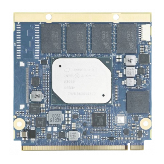
QSEVEN-Q7ALx2 - Preliminary User Guide, Rev. 0.7 5.2. Module Views Figure 3 : Top Side View Q7ALx2 CPLD connector Memory down MIPI-CSI2 Connector (shown here as vacant slot - option for some variants) Qseven® connector 4x Mounting points www.kontron.com // 19... -
Page 20: Figure 4 : Bottom Side View Q7Alx2
QSEVEN-Q7ALx2 - Preliminary User Guide, Rev. 0.7 Figure 4 : Bottom Side View Q7ALx2 Qseven® connector 4x Mounting points www.kontron.com // 20... -
Page 21: Component Technical Data
QSEVEN-Q7ALx2 - Preliminary User Guide, Rev. 0.7 5.3. Component Technical Data The table below summarizes the Q7ALx2 module’s main component technical features: Table 3: Component Technical Data Q7ALx2 Module Form Factor Qseven® module standardized form factor (70 mm x 70 mm) Processor System On Chip Embedded processors based on Intel x86 SoC with integrated chipset:... - Page 22 QSEVEN-Q7ALx2 - Preliminary User Guide, Rev. 0.7 Software BIOS On-board 128 Mb SPI flash for BIOS storage Windows® 10 Enterprise 64 bit Operating System Windows 10 IoT 64 bit Support Linux Yocto 64-bit I/O functions on Qseven® connector PCIe 4x PCIe Gen 2 (5 GT/s), lanes configured as: ...
-
Page 23: Environmental Condition
QSEVEN-Q7ALx2 - Preliminary User Guide, Rev. 0.7 Display Digital Displays Up to two independent digital displays using “DDI0” and “DDI1” from the SoC: DDI0 – eDP (no LVDS only shares Qseven® connector pin with LVDS ) DDI1 - DP++ or HDMI DDI0 eDP interface is DDI0 from SoC (Resolution: 3840x2160 @60Hz) HDMI... -
Page 24: Standards And Directives
QSEVEN-Q7ALx2 - Preliminary User Guide, Rev. 0.7 5.5. Standards and Directives The Qseven® Q7ALx2 module complies with the following Standards and Directive. Table 5: Standards and Directives National Certification CE Marking Directive 93/68/EEC Low Voltage Directive (LVD) 2006/95/EC EMC/EMI Emission EN 55032 Class B / Test conducted in standard available chassis with Q7 carrier board. -
Page 25: Mechanical Specification
QSEVEN-Q7ALx2 - Preliminary User Guide, Rev. 0.7 5.6. Mechanical Specification Figure 5 : Q7ALx2 Top Side Mechanical Specification (measurement in mm) Figure 6: Q7ALx2 Bottom Side Mechanical Specification (measurement in mm) www.kontron.com // 25... -
Page 26: Heat Spreader Mechanical Specification
QSEVEN-Q7ALx2 - Preliminary User Guide, Rev. 0.7 5.6.1. Heat Spreader Mechanical Specification Figure 7: Heat Spreader for Commercial Grade Mechanical Specification (measurement in mm) 5.42 5.17 5.66 Figure 8: Heat Spreader for Industrial Grade Mechanical Specification (measurement in mm) 5.42 4.17 5.66 www.kontron.com... -
Page 27: Thermal Management
QSEVEN-Q7ALx2 - Preliminary User Guide, Rev. 0.7 5.7. Thermal Management 5.7.1. Heatspreader Plate and Cooling Solutions A heatspreader plate assembly is available for the Q7ALx2. The heatspreader plate is NOT a heat sink. The heatspreader plate is a Qseven® standard thermal interface to accompany a heat sink or external cooling device(s). The aluminum slugs and thermal pads on the underside of the heatspreader plate act as thermal interfaces between the heatspreader plate and the major heat-generating components on the Q7ALx2 module. -
Page 28: Temperature Sensors
QSEVEN-Q7ALx2 - Preliminary User Guide, Rev. 0.7 5.7.2. Temperature Sensors The Hardware Monitor (HWM) chip (Nuvoton NCT802Y) uses an on-chip temperature sensor to measure the module’s temperature. This measurement is referred to as the “module temperature” in the BIOS setup menu (Advanced>H/W Monitor). -
Page 29: Power Specification
QSEVEN-Q7ALx2 - Preliminary User Guide, Rev. 0.7 5.8. Power Specification The Q7ALx2 module receives power from a carrier board via the Qseven® connector. The Q7ALx2 must be connected to a carrier board to power on. The Qseven® module is powered on by connecting to a carrier board using the Qseven® connector. -
Page 30: Input Power Sequencing
QSEVEN-Q7ALx2 - Preliminary User Guide, Rev. 0.7 5.8.4. Input Power Sequencing The following figure illustrates the Q7ALx2 module’s inputs power start and stop sequence requirements. Figure 11: Input Power Start and Stop Sequence VCC_RTC VCC_SB PWGIN PWGIN is an active high input for the Qseven® module and indicate that the all the power rails on the carrier board are ready for use. -
Page 31: Power Supply Control And Management Signals
QSEVEN-Q7ALx2 - Preliminary User Guide, Rev. 0.7 5.8.5.1. Power Supply Control and Management Signals Power supply control settings are set in the BIOS setup menus and enable the module to shut down, rest and wake from standby. Table 7: Power Supply Control and Management Signals Signal Description PWRBTN#... -
Page 32: 6/ Features And Interfaces
QSEVEN-Q7ALx2 - Preliminary User Guide, Rev. 0.7 6/ Features and Interfaces 6.1. CAN Bus The CAN Bus interface is compliant with the CAN Bus V 2.0 specification and implemented via a LPC to GPIO bridge. 6.2. eMMC (option) The Embedded Multimedia Flash Card (eMMC) is eMMC 5.1 compatible and supports eMMC flash capacities from 2 GByte to 32 GByte (SLC) or from 2 GByte to 64 GByte (MLC). -
Page 33: Kontron Security Solution (Option)
QSEVEN-Q7ALx2 - Preliminary User Guide, Rev. 0.7 6.6. Kontron Security Solution (option) Kontron Security Solution is a combined hardware and software solution that includes an embedded hardware security module and a software framework to protect applications. The integrated security module connected to SoC port 7. Therefore, if this option is installed, SoC port 7 is not available for other interfaces. -
Page 34: Rtc
QSEVEN-Q7ALx2 - Preliminary User Guide, Rev. 0.7 6.8. The Real Time Clock (RTC) accurately keeps track of the current time. The RTC’s low power consumption means that the RTC can be powered from an alternative source of power, enabling the RTC to continue to keep time while the primary source of power is off or unavailable. -
Page 35: Speedstep™ Technology
QSEVEN-Q7ALx2 - Preliminary User Guide, Rev. 0.7 SPI boot is available for multiple vendors. The following table lists the supported SPI Boot Flash types for the 8-SOIC package. Table 10: Supported SPI Boot Flash Types for 8-SOIC Package Size Manufacturer Part Number Device ID 16MB... -
Page 36: Uart
QSEVEN-Q7ALx2 - Preliminary User Guide, Rev. 0.7 6.13. UART The 4-wire UART supported by MAX10 FPGA implements a serial communication interface (COM) and supports one serial RX/TX port on the Qseven® connector’s pin-171 (UART0_TX) and pin-177 (UART0_RX) for UART0. The UART controller is fully 16550A compatible. -
Page 37: 7/ System Resources
QSEVEN-Q7ALx2 - Preliminary User Guide, Rev. 0.7 7/ System Resources 7.1. PCI Devices All devices follow the Peripheral Component Interconnect (PCI) 2.3 and PCI Express Base 1.0a specification. The BIOS and Operating System (OS) control the memory and I/O resources. For more information, refer to the PCI 2.3 Specification. -
Page 38: 8/ Connectors
QSEVEN-Q7ALx2 - Preliminary User Guide, Rev. 0.7 8/ Connectors 8.1. MIPI Connector Pin Assignment (option for some variants) Figure 12 : MIPI CSI2 Connector Table 14: MIPI-CSI2 Connector Pin Assignment Signal Signal CAM_PWR 3.3V CAM0_I2C_DAT CAM_PWR 3.3V CAM0_ENA# CAM0_CSI_D0+ MCLK CAM0_CSI_D0- CAM1_ENA# CAM1_I2C_CLK... -
Page 39: Qseven® Connector Pin Assignment
QSEVEN-Q7ALx2 - Preliminary User Guide, Rev. 0.7 Table 15: CPLD Connector Pin Assignment Signal 3.3V 8.3. Qseven® Connector Pin Assignment The Qseven® connector is MXM 230-pin connector with the same number of pins on the module’s top and bottom sides, see Figure 3, pos. 3 and Figure 4, pos. 1. Table 16: QSEVEN Connector Pin Assignment Signal (Bottom side row) Signal (Top side row) - Page 40 QSEVEN-Q7ALx2 - Preliminary User Guide, Rev. 0.7 Signal (Bottom side row) Signal (Top side row) SDIO_DAT2 Reserved Reserved Reserved Reserved USB_OTG_PEN HDA_SYNC / I2S_WS SMB_CLK / GP1_I2C_CLK HDA_RST# / I2S_RST# SMB_DAT / GP1_I2C_DAT HDA_BITCLK / I2S_CLK SMB_ALERT# HDA_SDI / I2S_SDI GP0_I2C_CLK HDA_SDO / I2S_SDO GP0_I2C_DAT...
- Page 41 QSEVEN-Q7ALx2 - Preliminary User Guide, Rev. 0.7 Signal (Bottom side row) Signal (Top side row) DP_LANE1+ / TMDS_LANE1+ DP_AUX+ DP_LANE1- / TMDS_LANE1- DP_AUX- DP_LANE2+ / TMDS_LANE0+ USB_SSRX1- DP_LANE2- / TMDS_LANE0- USB_SSRX1+ DP_LANE0+ / TMDS_LANE2+ HDMI_CTRL_DAT DP_LANE0- / TMDS_LANE2- HDMI_CTRL_CLK HDMI_HPD# DP_HPD# PCIE_CLK_REF+ PCIE_WAKE#...
- Page 42 QSEVEN-Q7ALx2 - Preliminary User Guide, Rev. 0.7 Signal (Bottom side row) Signal (Top side row) www.kontron.com // 42...
-
Page 43: 9/ Power On
QSEVEN-Q7ALx2 - Preliminary User Guide, Rev. 0.7 9/ Power on The Q7ALx2 module receives power from a carrier board via the Qseven® connector. The Q7ALx2 must be connected to a carrier board to power on and power off. The Qseven® module is powered on by connecting to a carrier board using the Qseven® connector. -
Page 44: 10/ Uefi Bios
QSEVEN-Q7ALx2 - Preliminary User Guide, Rev. 0.7 uEFI BIOS 10.1. Starting the uEFI BIOS The Q7ALx2 module uses a Kontron-customized, pre-installed and configured version of Aptio ® V uEFI BIOS based on the Unified Extensible Firmware Interface (uEFI) specification and the Intel® Platform Innovation Framework for EFI. This uEFI BIOS provides a variety of new and enhanced functions specifically tailored to the hardware features of the Q7ALx2 module. -
Page 45: Setup Menus
QSEVEN-Q7ALx2 - Preliminary User Guide, Rev. 0.7 10.2. Setup Menus The Setup utility features menus listed in the selection bar at the top of the screen are: Main Advanced Chipset Security Boot Save & Exit The currently active menu and the currently active uEFI BIOS setup item are highlighted in white. -
Page 46: Table 18: Main Setup Menu Sub-Screens And Functions Example
QSEVEN-Q7ALx2 - Preliminary User Guide, Rev. 0.7 The following table shows the Main setup menu sub-screens and functions and describes the content. The BIOS features in this user guide are open to change and may not be the latest version. The latest version may have differences to the options and features described in Table 18. -
Page 47: Advanced Setup Menu
QSEVEN-Q7ALx2 - Preliminary User Guide, Rev. 0.7 10.2.2. Advanced Setup Menu The Advanced setup menu displays sub-screens and second level sub-screens with functions, for advanced configurations. Setting items, on this screen, to incorrect values may cause system malfunctions. Figure 16: Advanced Setup Menu Initial Screen Example The following table shows the Advanced sub-screens and functions and describes the content. - Page 48 QSEVEN-Q7ALx2 - Preliminary User Guide, Rev. 0.7 Sub-Screen Function Second level Sub-Screen / Description Trusted Available PCR Read only field Computing> Banks> Displays available PCR Banks (continued) SHA-1 PCR Bank> SHA-1 PCR Bank [Enabled, Disabled] SHA256 PCR SHA256 PCR Bank Bank>...
- Page 49 QSEVEN-Q7ALx2 - Preliminary User Guide, Rev. 0.7 Sub-Screen Function Second level Sub-Screen / Description Serial Port Console COM2 Console Console redirection via QSEVEN module’s COM3 Redirection> Redirection> [Enabled, Disabled] (continued) COM3 Console Console redirection via QSEVEN module’s COM4 Redirection> [Enabled, Disabled] Additional Information COM # Console If redirection is enabled then the port settings such as Terminal type, Bits per second, Data bits, Parity etc.
- Page 50 QSEVEN-Q7ALx2 - Preliminary User Guide, Rev. 0.7 Sub-Screen Function Second level Sub-Screen / Description SDIO SDIO Access Option: Access SD device in PIO mode. Configuration> Mode> [Auto, ADMA, SDMA, PIO] (continued) (continued) Mass storage Mass storage device emulation type. devices> [Auto, Floppy, Forced FDD, Hard Disk] USB Configuration>...
- Page 51 QSEVEN-Q7ALx2 - Preliminary User Guide, Rev. 0.7 Sub-Screen Function Second level Sub-Screen / Description Hardware Monitor> System Fan – Displays number of pulses the fan produces during one revolution. (continued) Fan Pulse> (Range: 1-4) System Fan - Sets System Fan Control mode Control Mode>...
- Page 52 QSEVEN-Q7ALx2 - Preliminary User Guide, Rev. 0.7 Sub-Screen Function Second level Sub-Screen / Description Thermal Passive TC2 Sets TC2 value for the ACPI Passive Cooling Formula.(Range: 1 – 16) Configuration Value> Parameters> Passive TSP Sets TSP value for the ACPI Passive Cooling Formula.(Range: 2 – 32) (continued) Value>...
- Page 53 QSEVEN-Q7ALx2 - Preliminary User Guide, Rev. 0.7 Sub-Screen Function Second level Sub-Screen / Description Debug Persistent RAM Specify the amount of main memory to be reserved for Pram. Configuration> size> [4MB, 16MB, 64MB, Disable] (continued) OS DnX focus Enable OS Dnx entry>...
-
Page 54: Chipset Setup Menu
QSEVEN-Q7ALx2 - Preliminary User Guide, Rev. 0.7 10.2.3. Chipset Setup Menu The Chipset setup menu lists four sub-screen options North bridge, South bridge, Uncore Configuration and South Cluster Configuration. 10.2.3.1. Chipset> North Bridge Figure 17: Chipset > North Bridge Menu Initial Screen Example The following table shows the North bridge sub-screens and functions and describes the content. -
Page 55: Chipset > South Bridge
QSEVEN-Q7ALx2 - Preliminary User Guide, Rev. 0.7 10.2.3.2. Chipset > South Bridge Figure 18: Chipset>South Bridge Menu Initial Screen Example The following table shows the South Bridge sub-screens and functions, and describes the content. Default settings are in bold. The BIOS features in this user guide are open to change and may not be the latest version. The latest version may have differences to the options and features described in Table 21. -
Page 56: Chipset> Uncore Configuration
QSEVEN-Q7ALx2 - Preliminary User Guide, Rev. 0.7 10.2.3.3. Chipset> Uncore Configuration Figure 19: Chipset>Uncore Configuration Menu Initial Screen Examples The following table shows the Uncore Configuration sub-screens and functions and describes the content. Default settings are in bold. www.kontron.com // 56... -
Page 57: Table 22: Chipset Set> Uncore Configuration Sub-Screens And Functions
QSEVEN-Q7ALx2 - Preliminary User Guide, Rev. 0.7 The setup menu screens may not be the latest version. The latest version may have certain differences to the options and features described in Table 22. Table 22: Chipset Set> Uncore Configuration Sub-screens and Functions Function Second level Sub-Screen / Description GOP Driver>... - Page 58 QSEVEN-Q7ALx2 - Preliminary User Guide, Rev. 0.7 Function Second level Sub-Screen / Description IGD Flat Panel> [Auto, 640x480, 800x600, 1024x768, 1280x1024, 1366x768, 1680x1050, 1920x1200, 1280x800] IGD Boot Type> Select preference for IGD display interface used when system boots. [Auto, VGA port, HDMI, DP Port B, Dp Port C, eDP, DSI Prt A, DSI Port C] Panel Scaling>...
-
Page 59: Chipset> South Cluster Configuration
QSEVEN-Q7ALx2 - Preliminary User Guide, Rev. 0.7 10.2.3.4. Chipset> South Cluster Configuration Figure 20: Chipset>South Cluster Configuration Menu Initial Screen Example The following table shows the South Cluster Configuration sub-screens and functions and describes the content. Default settings are in bold and for some functions, additional information is included. The BIOS features in this user guide are open to change and may not be the latest version. - Page 60 QSEVEN-Q7ALx2 - Preliminary User Guide, Rev. 0.7 Function Second level Sub-Screen / Description HD Audio WoV (Wake on [BIT6] – BT Intel A2DP Configuration> Voice) > [BIT9] – Context Aware (continued) (continued) [Enabled, Disabled] Bluetooth DSP Feature. Sideband> Bitmask structure: [BIT0] –...
- Page 61 QSEVEN-Q7ALx2 - Preliminary User Guide, Rev. 0.7 Function Second level Sub-Screen / Description HD Audio Context Aware> [BIT2] – Codec based VAD Configuration> (continued) [BIT3] – SRAM Reclaim (continued) [BIT5] – BT Intel HFP [BIT6] – BT Intel A2DP [Enabled, Disabled] NHLT Endpoints Configuration: DMIC>...
- Page 62 QSEVEN-Q7ALx2 - Preliminary User Guide, Rev. 0.7 Function Second level Sub-Screen / Description HD Audio Enables/Disables 3rd Party Processing Module Support (identlfied Samsung EQ/DRC> Configuration> by GUID). WoV must be enabled as a feature first to selecr relevent ForteMedia WoV IP. [Enabled, Disabled] (continued) SAMSoft>...
- Page 63 QSEVEN-Q7ALx2 - Preliminary User Guide, Rev. 0.7 Function Second level Sub-Screen / Description LPSS LPSS HSUART1 LPSS HSUART1 Support Configuration> Support (D24:F1)> [Enable, Disable] (continued) LPSS HSUART2 LPSS HSUART2 Support Support (D24:F2)> [Enable, Disable] LPSS SPI0 Support LPSS SPI0 Support (D25:F0)>...
- Page 64 QSEVEN-Q7ALx2 - Preliminary User Guide, Rev. 0.7 Function Second level Sub-Screen / Description PCI Express PCI Root Port 4 SECE> Root PCI Express System Error on correctable Configuration> (GbE)> error (contined) [Enabled, Disabled] PCI Root Port 5 PME SCI> PCI Express PME SCI (NC) [Enabled, Disabled] Hot Plug>...
- Page 65 QSEVEN-Q7ALx2 - Preliminary User Guide, Rev. 0.7 Function Second level Sub-Screen / Description SATA Drivers> SATA Port 0> SATA Port # Hot Reports SATA port as being Hot Plug capable (continued) Plug Capability> [Enabled, Disabled] SATA Port 1> (continued) SCC SD Card Support SCC card support Configuration>...
- Page 66 QSEVEN-Q7ALx2 - Preliminary User Guide, Rev. 0.7 Function Second level Sub-Screen / Description Miscellaneous DCI Auto Detect If set, DCI Auto detects if DCI is connected during BIOS post time and Configuration> Enable> enables DCI. If not set, DCI is disabled. (continued) [Enabled, Disabled] GPIO Lock>...
-
Page 67: Security Setup Menu
QSEVEN-Q7ALx2 - Preliminary User Guide, Rev. 0.7 10.2.4. Security Setup Menu The Security setup menu provides information about the passwords and functions for specifying the security settings such as Hard Disk user and master passwords. Figure 21: Security Setup Menu Initial Screen Example The following table shows the Security sub-screens and functions and describes the content. - Page 68 QSEVEN-Q7ALx2 - Preliminary User Guide, Rev. 0.7 Function Description HDD Security Configuration Security Frozen (continued) HDD User Pwd Status Not Installed HDD Master Pwd Status Installed Set User Sets HDD password. Password> Note: It is advisable to power cycle the system after setting Hard Disk passwords.
-
Page 69: Remember The Password
QSEVEN-Q7ALx2 - Preliminary User Guide, Rev. 0.7 10.2.4.1. Remember the Password It is recommended to keep a record of all passwords in a safe place. Forgotten passwords results in the user being locked out of the system. If the system cannot be booted because the User Password or the Supervisor Password are not known, clear the uEFI BIOS settings, or contact Kontron Support for further assistance. -
Page 70: Boot Setup Menu
QSEVEN-Q7ALx2 - Preliminary User Guide, Rev. 0.7 10.2.5. Boot Setup Menu The Boot setup menu lists the dynamically generated boot-device priority order. Figure 22: Boot Setup Menu Initial Screen Example The following table shows the Boot set up sub-screens and functions and describes the content. Default settings are in bold. - Page 71 QSEVEN-Q7ALx2 - Preliminary User Guide, Rev. 0.7 Function Description VGA Support> If Auto, only install Legacy OpRom with Legacy OS and logo would NOT be shown during post. Efi driver will still be installed with EFI OS. [Auto, EFI Driver] USB Support>...
-
Page 72: Save And Exit Setup Menu
QSEVEN-Q7ALx2 - Preliminary User Guide, Rev. 0.7 10.2.6. Save and Exit Setup Menu The Save and Exit setup menu provides functions for handling changes made to the settings and exiting the program. Figure 23: Save and Exit Setup Menu Initial Screen Example The following table shows the Save and Exit sub-screens and functions and describes the content. -
Page 73: The Uefi Shell
QSEVEN-Q7ALx2 - Preliminary User Guide, Rev. 0.7 10.3. The uEFI Shell The Kontron uEFI BIOS features a built-in and enhanced version of the uEFI Shell. For a detailed description of the available standard shell scripting, refer to the EFI Shell User Guide. For a detailed description of the available standard shell commands, refer to the EFI Shell Command Manual. -
Page 74: Uefi Shell Scripting
QSEVEN-Q7ALx2 - Preliminary User Guide, Rev. 0.7 10.4. uEFI Shell Scripting 10.4.1. Startup Scripting If the <ESC> key is not pressed and the timeout has run out then the uEFI Shell automatically tries to execute some startup scripts. It searches for scripts and executes them in the following order: Initially searches for Kontron flash-stored startup script. -
Page 75: Firmware Update
QSEVEN-Q7ALx2 - Preliminary User Guide, Rev. 0.7 10.5. Firmware Update Firmware updates are typically delivered as a ZIP archive containing only the firmware images. The content of the archive with the directory structure must be copied onto a data storage device with FAT partition. 10.5.1. -
Page 76: Appendix A: List Of Acronyms
QSEVEN-Q7ALx2 - Preliminary User Guide, Rev. 0.7 Appendix A: List of Acronyms Table 27: List of Acronyms ACPI Advanced Configuration and Power Local Area Network Interface Low Pin-Count Interface: BIOS Basic Input Output System Line Printing Terminal Controller-area network Least Significant Bit Carrier Application specific circuit board that LVDS... -
Page 77: About Kontron
QSEVEN-Q7ALx2 - Preliminary User Guide, Rev. 0.7 About Kontron Kontron is a global leader in IoT/Embedded Computing Technology (ECT). As a part of technology group S&T, Kontron, together with its sister company S&T Technologies, offers a combined portfolio of secure hardware, middleware and services for Internet of Things (IoT) and Industry 4.0 applications.
Need help?
Do you have a question about the kontron QSEVEN-Q7AL 2 Series and is the answer not in the manual?
Questions and answers