Table of Contents

Related Manuals for Aspen RMC-800


Summary of Contents for Aspen RMC-800
- Page 1 24 St. Martin Dr. Marlborough, MA 01752 Installation and Operation Instructions Rack Mount Chiller (RMC-800, RMC-1100) FP00091, FP00101 Installations Notes Date of Purchase Date of Installation Installer Model Number Serial Number...
-
Page 2: Table Of Contents
Warnings ............................. 11 Communication ............................11 Maintenance ............................... 14 Customer Service ............................14 Commercial Product Warranty ....................... 14 Warranty Repairs ............................ 15 Technical Support ........................... 15 Aspen Contact Information ........................15 OM00020 Rev 2, FP00091, FP00101 Operation Manual Page 2 of 15... -
Page 3: System Information
System Information The Rack Mount Chiller (RMC-800, RMC-1100) is a turn key 2U (3.5 in. tall) chiller system. The RMC provides a user interface to control the coolant setpoint, pump speed and alarm settings. The system maintains coolant supply temperature with a PID loop that varies the compressor speed. Details on the system interface and performance are included below. -
Page 4: General Operation
55.9 x 48.3 x 9.0 cm (22.0 x 19.0 x 3.5 in) Coolant Interface Aspen recommends using Koolance 702 as the working fluid for this system. The use of water without additives may result in corrosion and/or biological growth in an untreated system. The coolant and customer coolant loop should be clean and free of debris. -
Page 5: Draining
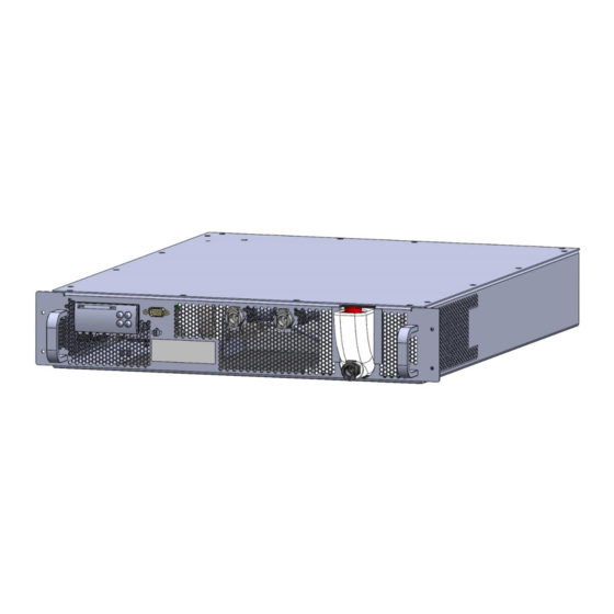
The RMC is a rack mount chiller (2U). The outer dimensions and mounting dimensions are defined in Figure 3. Some customers may wish to have the RMC as a desktop unit, and for that, Aspen can recommend adhesive feet for the unit. -
Page 6: Electrical Interface
Electrical Interface Input Voltage 120 VAC or 240 VAC (24 VDC available upon request from Aspen but is dimensionally different). Input voltage is specified at time of purchase with Aspen. Maximum Power 600 W (5 A at 120 VAC, 2.5 A at 24 VDC) -
Page 7: Coolant Flow Rate
Figure 5: RMC-1100 Performance Map Figure 6: RMC-800 Performance Map Coolant Flow Rate The RMC is equipped with a positive displacement pump. Using Koolance 702 as a coolant, the system can generate the following maximum flow curve. The speed of the pump may be reduced should the user desire less flow. -
Page 8: Controller Interface
Figure 7: RMC Pressure/ Flow Curve The RMC is equipped with a bypass valve to prevent the pump from generating excessive pressures. The bypass valve begins to crack around 4.0 bar (58 psig). The bypass valve will prevent the system (and external components) from seeing pressures greater than 6.9 bar (100 psig). -
Page 9: Starting The Rmc
Press 3 times to reach the PAR screen. Press Press 1 time to reach the CFG screen. Press Press on the Set screen. Use the arrows to adjust the setpoint. Press Press 3 times to return to the main screen. Starting the RMC To start the system, the user must do the following: Press... -
Page 10: Parameter Tree
Press 4 times to return to the main screen. Parameter Tree The table below represents all the functionality of the controller. Some items are only accessible by entering the login password (see Controller Login p. 11): Table 1: RMC Controller Tree Level 1 Level 2 Level 3... -
Page 11: Controller Login
Controller Login The user can access the hidden functionality of the system by entering the login password (default is 947). System Errors The RMC has a handful of faults and warnings which are displayed on the controller and will shut down the system when triggered. - Page 12 Table 4: RMC RS-485 Communication Pinout Pin 2 – RX/D- Pin 3 – TX/D+ Pin 5 - GND The default communications settings are as follows, but they can be adjusted if required. Serial address: 1 Serial baudrate: 19200 The relevant parameters for the RMC and their Application Data Unit (ADU) are defined in the Table 1 below: Table 5: Modbus parameters LABEL...
- Page 13 Integral Time 10000 3024 Status var > MCX Design Hotspots SystemOnOff -32768 32767 Read 8101 Reset Alarms 1859 PUMP STATUS -32768 32767 Read 8102 UnitFault -32768 32767 Read 8103 COMPRESSOR STATUS -32768 32767 Read 8104 COMPRESSOR RUN -2^31 2^31 Read 8105 PUMP STATUS -32768...
-
Page 14: Maintenance
Aspen at buyer’s expense, transportation charges prepaid. Aspen’s sole obligation under its warranty shall be, at its option, to repair, replace or refund the price of any product thereof which is proved to violate such warranty. In no event, whether based on contract,... -
Page 15: Warranty Repairs
Aspen Systems, LLC. Depending on the circumstances of the problem, it may be deemed necessary to return the products to Aspen Systems. for repair. In order to return the product for repair, please contact Aspen Systems via email, telephone, or through the Aspen Systems’ website (see Contact...
Need help?
Do you have a question about the RMC-800 and is the answer not in the manual?
Questions and answers