Table of Contents
Advertisement
Quick Links
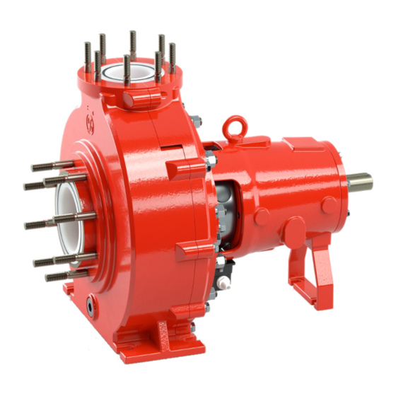
X-CLASS HEAVY DUTY PUMP
Standardized pump NX for
chemicals DIN EN ISO 2858
Standardized Close-coupled
plastic pump BX for chemicals
according to DIN EN ISO 2858
Original operating manual
Version
BA-2019.04.17 EN
Print-No.
300 785
TR MA DE Rev003
NX / BX series
STÜBBE GmbH & Co. KG
Hollwieser Straße 5
32602 Vlotho
Germany
Phone: +49 (0) 5733-799-0
Fax: +49 (0) 5733-799-5000
E-mail:
contact@stuebbe.com
Internet:
www.stuebbe.com
Subject to technical modifications.
Read carefully before use.
Save for future use.
Advertisement
Table of Contents
Troubleshooting

Subscribe to Our Youtube Channel
Related Manuals for Stübbe NX Series


Summary of Contents for Stübbe NX Series
- Page 1 X-CLASS HEAVY DUTY PUMP Standardized pump NX for chemicals DIN EN ISO 2858 Standardized Close-coupled plastic pump BX for chemicals according to DIN EN ISO 2858 Original operating manual NX / BX series Version BA-2019.04.17 EN STÜBBE GmbH & Co. KG Print-No.
-
Page 2: Table Of Contents
Table of contents Table of contents About this document ....... 5 5.5.1 Preparing the connection (NX) . - Page 3 Table of contents Restoring the pump to service ....32 Maintenance ......... 33 Inspections .
- Page 4 Table of contents List of figures Tab. 9 Designation of components according to part numbers ........42 Tab.
-
Page 5: About This Document
About this document About this document Other applicable documents This manual • is part of the equipment To download: ATEX additional manual (300 365) • applies to all series referred to Additional instructions for use in • describes safe and proper operation during all operating explosive atmospheres phases www.stuebbe.com/pdf_manuals/300365.pdf... -
Page 6: Warnings And Symbols
About this document Warnings and symbols Symbol Meaning • Immediate acute risk • Death, serious bodily harm • Potentially acute risk • Death, serious bodily harm • Potentially hazardous situation • Minor injury • Potentially hazardous situation • Material damage Safety warning sign Take note of all information highlighted by the safety warning... -
Page 7: General Safety Instructions
General safety instructions General safety instructions • If pumps are delivered without motors, then final assembly as a pump assembly must take place in accordance with the provisions of the Machinery Directive 2006/42/EC. The manufacturer accepts no liability for damages caused •... -
Page 8: General Safety Instructions
General safety instructions General safety instructions • Make sure that trainee personnel only work on the pump under supervision of specialist technicians. Observe the following regulations before carrying out any work. Safety equipment • Provide the following safety equipment and verify its func- 2.2.1 Product safety tionality:... -
Page 9: Specific Hazards
General safety instructions Specific hazards 2.3.1 Hazardous pumped liquids • When handling hazardous fluids, observe the safety regu- lations for the handling of hazardous substances. • Use personal protective equipment when carrying out any work on the pump. • Collect leaking pumped liquid and residues in a safe man- ner and damage them in accordance with environmental regulations. -
Page 10: Layout And Function
Layout and Function Layout and Function 3.1.2 ATEX type plate Hollwieser Str.5 Marking D-32602 Vlotho 3.1.1 Name plate Type Serial-No. ID.NO. Hollwieser Str.5 D-32602 Vlotho ø Type ø B (orifice) Serial-No. ρ kg/dm ID.NO. GLRD ø ø B (orifice) ρ kg/dm GLRD Fig. -
Page 11: Pump Type Code
Layout and Function 3.1.3 Pump type code 3.1.4 – Mechanical seal type code 80 50 315 D Fig. 4 Mechanical seal type code (example) Version • E – Single acting mechanical seal • Q – Single acting mechanical seal with quench Fig. -
Page 12: Description
Layout and Function Description 3.2.1 NX /BX pump Metalclad chemical standard pumps, plastic, in process design. The NX pump corresponds to standard DIN ISO 2858 for pres- sure rating PN16. The sizes NX 40-25-160, NX 100-65-315 and NX 250-200-400 are based on the standard (transnorm pumps). -
Page 13: Assembly
Layout and Function Assembly 3.3.1 1 4 5 6 Fig. 5 Version NX Armored casing of GGG40.3 Volute casing of plastic Discharge flange Sealing insert of plastic Mechanical seal Splash guard Bearing casing of GGG40.3 Shaft of steel (1.7227) Coupling 10 Coupling guard 11 Support foot 12 Leakage tray with drain connection... -
Page 14: Fig. 6 Version Bx
Layout and Function 3.3.2 1 4 5 6 7 8 9 Fig. 6 Version BX Armored casing of GGG40.3 Volute casing of plastic Discharge flange Sealing insert of plastic Mechanical seal Splash guard Bearing casing of GGG40.3 Hollow shaft Coupling 10 Support foot 11 Leakage tray with drain connection 12 Impeller of plastic... -
Page 15: Shaft Seals
Layout and Function Shaft seals B) Version with internal flushing and quenching – API plan 62 type QSTN Only one of the following shaft seals can be used • Atmosphere-side seal of the bellows carrier (482) by radial (→ 3.1.4 – Mechanical seal type code, Page 11). seal (421.3) •... -
Page 16: Fig. 9 Single Acting Mechanical Seal, Continuous
Layout and Function C) Version with continuous flushing – API plan 32 D) Version for flushing after use, type ESTS type ESTD • For use with pumped media containing solids, where for • Suitable for pumping media containing solids process reasons the use of flushing media is prohibited •... -
Page 17: Single-Acting Stübbe Mechanical Seal, Type
Layout and Function 3.4.2 Single-acting STÜBBE mechanical seal, type UV2 3.4.3 Double-acting STÜBBE mechanical seal, type UV3 / Metax G-SBA • General-purpose chemical resistance • General-purpose chemical resistance • Sturdy high-pressure spring single mechanical seal in REA version • Sturdy high-pressure spring double mechanical seal in REA version •... -
Page 18: Transport, Storage And Disposal
Transport, Storage and Disposal Transport, Storage and Disposal Transport The user/owner is responsible for the transport of the pump. Weight specifications (→ documents for the particular order) 4.1.1 Unpacking and inspection on delivery 1. Unpack the pump/pump assembly upon delivery and inspect it for transport damage. -
Page 19: Storage
Transport, Storage and Disposal Storage NOTE Material damage due to inappropriate storage! Store the pump properly. 1. Seal all openings with blind flanges, blind plugs or plastic covers. 2. Make sure the storage room meets the following condi- tions: – –... -
Page 20: Installation And Connection
Installation and connection Installation and connection 5.1.3 Prepare foundation and surface Aids, tools, materials: – Steel shims For pumps in potentially explosive atmospheres (→ ATEX – Spirit level additional manual). Installation options: – With concrete foundation NOTE – With steel foundation frames –... -
Page 21: Attaching Pump Unit
Installation and connection Installing without foundation Only allowed if pump is provided for installation without foundation (→ order data sheet). Attachment methods must be designed so that undesirable displacement of the pump is prevented. When installed on machine feet, the operational stability is achieved by the weight of the pump itself and the rigidity of the attached pipework. -
Page 22: Planning The Electrical System
Installation and connection Planning the electrical system 5.5.3 Installing the coupling guard (NX) The (heavy-duty) coupling guard consists of the pump side cou- Ensure the following in the electrical supply to the pump pling guard and the motor side coupling guard. unit: –... -
Page 23: Making The Electrical Connections To The Motor (Nx)
Installation and connection 5.5.4 Making the electrical connections to 5.5.5 Check direction of rotation (NX) the motor (NX) DANGER Follow the instructions of the motor manufacturer. Risk of electrocution! All electrical work must be carried out only by qualified elec- tricians. -
Page 24: Removing The Coupling Guard (Nx)
Installation and connection 5.5.6 Removing the coupling guard (NX) 2. Assemble together the hub body (1), gear ring (3) and inter- mediate piece (4). The (heavy-duty) coupling guard consists of the pump side cou- 3. Fit the assembly with the half shells (5) to the ends of the pling guard and the motor side coupling guard. -
Page 25: Aligning The Coupling Precisely (Nx)
Installation and connection Connecting the BX pump 5.5.9 Aligning the coupling precisely (NX) Comply with the tolerance values for fine adjustment of 5.6.1 Preparing the connection (BX) the coupling (→ 9.2.4 Tolerance values for adjusting the coupling, Page 49). The sequence of operations for preparation of the connection differs depending on the installation situation. -
Page 26: Make The Electrical Connections To The Motor (Bx)
Installation and connection 5.6.3 Make the electrical connections to the motor (BX) 5.6.4 Check direction of rotation (BX) Follow the instructions of the motor manufacturer. DANGER Risk of electrocution! All electrical work must be carried out only by qualified elec- DANGER tricians. -
Page 27: Install The Coupling (Bx)
Installation and connection 5.6.5 Install the coupling (BX) 5.6.6 Installing motor (BX) The coupling adapter is pre-installed on the hollow shaft of the NOTE pump. Material damage through bangs and knocks! Do not bang and knock pump components. NOTE 1. Mount the motor on the bearing bracket, ensuring that the Material damage through bangs and knocks! coupling halves of the motor shaft are mated correctly with When pushing the coupling half on, do not allow it to... -
Page 28: Specifying Nominal Widths
Installation and connection 5.7.2 Specifying nominal widths 5.7.4 Provide self-priming container Keep the flow resistance in the pipes as low as possible. A self-priming container can be used to make the pump self-priming. 1. Ensure nominal suction pipe width is not smaller than the 1. -
Page 29: Discharging Leaks
Installation and connection 5.7.9 Discharging leaks Provide dry run protection In order to protect the pump from dry running and resulting WARNING damage – Provide dry run protection Risk of injury and poisoning due to hazardous pumped – e.g. STÜBBE PTM pressure and temperature monitor- liquids! ing sensor Safely collect any leaking pumped liquid, then discharge... -
Page 30: Installing The Suction Pipework
Installation and connection 5.8.3 Installing the suction pipework 1. Remove the transport and sealing covers from the pump. 2. Fit suction pipe stress-free and sealed. (→ 9.2.6 Flange tightening torques, Page 50). 3. Ensure no seals protrude inwards. 4. During suction operation, proceed as follows: –... -
Page 31: Operation
Operation Operation Commissioning 6.2.1 Switching on For pumps in potentially explosive atmospheres (→ ATEX Pump set up and connected properly additional manual). Check direction of rotation Coupling and coupling guard installed Motor set up and connected properly Preparing for commissioning Align motor precisely to the pump 6.1.1 Check downtimes... -
Page 32: Switching Off
Operation NOTE Take the following measures whenever the pump is shut down: Material damage as a result of dry running Ensure that the pump is properly filled and ventilated. Pump is Action shut down Take measures appropriate for 1. Turn on auxiliary systems (if present). the fluid (→... -
Page 33: Maintenance
Maintenance Maintenance Servicing DANGER For pumps in potentially explosive atmospheres (→ ATEX additional manual). Risk of injury due to running pump! Do not touch the pump when it is running. Trained service technicians are available for fitting and Do not carry out any work on the pump when it is running. repair work. -
Page 34: Maintenance In Accordance With Maintenance Schedule
Maintenance 7.2.1 Maintenance in accordance with main- tenance schedule Perform maintenance work in accordance with the mainte- nance schedule. Designation Interval Maintenance Pump assembly daily Check for increased noise development. Check for vibration. Pay attention to increased current consumption of the motor. Check that the anchor bolts are correctly seated. -
Page 35: Lubricate Bearings
Maintenance 7.2.2 Lubricate bearings Oil-lubricated bearings Lubrication of the bearings is required only for the pump type NOTE The pump is delivered without a filling of oil! Use suitable lubricants (→ 9.2.9 Lubricant, Page 51). Bearings may be damaged due to lack of oil lubrication or lubri- cation with the wrong oil. -
Page 36: Dismounting
Maintenance Dismounting NOTE Material damage due to incorrect dismounting/installation DANGER of the pump. Only specialist mechanics should complete dismounting/ Risk of injury due to running pump! installation work. Do not touch the pump when it is running. 7.3.1 Preparations for dismounting Do not carry out any work on the pump when it is running. -
Page 37: Troubleshooting
Troubleshooting Troubleshooting For pumps in potentially explosive atmospheres (→ ATEX additional manual). If faults occur which are not specified in the following table or cannot be traced back to the specified causes, please consult the manufacturer. Possible faults are identified by a fault number in the table below. - Page 38 Troubleshooting Fault number Possible cause Remedy – – – – Proportion of gas too high: pump is Consult the manufacturer. cavitating – – – – Pump running in the wrong direction Change over any two phases in the motor. – –...
- Page 39 Troubleshooting Fault number Possible cause Remedy – – – – Pressure-side fitting opened too wide Throttle down the flow rate at the pres- sure-side fitting. Observe the minimum flow rate (→ Tab. 26 Volumetric flow of the pumped medium, Page 54). Machine the impeller down.
-
Page 40: Tab. 8 Troubleshooting List
Troubleshooting Fault number Possible cause Remedy – – – – – – – Medium temperature too close to boiling Repair the pump. point (single-acting mechanical seal running Modify the single-acting mechanical seal hot) in consultation with the manufacturer so that it operates with continuous flushing/quenching, or convert it to a double-activing mechanical seal. -
Page 41: Appendix
Appendix Appendix Part no. Designation Replacement parts Spring 9.1.1 Part no. and description Bellows Gaiter bearer Part no. Designation 506.1 Retaining ring Volute casing 506.2 Retaining ring Motor flange adapter Liquid splash ring 155.1 Reinforced casing 511.1 Centering ring 155.2 Reinforced casing Insert ring Support foot... - Page 42 Appendix Part no. Designation 902.8 Stud bolt 903.1 Plug screw 903.25 Plug screw 912.3 Plug screw 914.3 Cylinder screw 914.6 Cylinder screw 914.7 Cylinder screw 914.9 Cylinder screw 914.10 Cylinder screw 914.12 Cylinder screw 914.26 Cylinder screw 914.31 Cylinder screw 914.37 Cylinder screw 920.1...
-
Page 43: Sectional Drawing Nx
Appendix 9.1.2 Sectional drawing NX 554.1 902.1 920.1 412.01 155.1 412.03 412.07 481 412.08 558.8 902.8 920.8 412.04 900.35 412.05 412.06 506.1 412.02 940.2 554.2 558.6 902.2 554.6 920.2 901.6 420.2 940.1 554.4 558.4 912.3 210 475 472 321 330 932 914.7 183 580.1 900.14... -
Page 44: Sectional Drawing Bx
Appendix 9.1.3 Sectional drawing BX 554.1 558.8 902.1 902.8 412.03 412.07 412.08 900.35 321 361 920.1 920.8 412.01 155.1 412.04 412.05 506.1 554.2 902.2 920.2 412.02 554.4 580.1 421.24 912.3 506.2 558.4 412.06 420.1 901.7 420.2 554.26 412.23 562.1 901.41 902.4 511.1 914.37... -
Page 45: Technical Specifications
Appendix Technical specifications Further technical data (→ data sheet). 9.2.1 Ambient conditions Operation under any other ambient conditions should be agreed with the manufacturer. Tempera- Relative humidity [%] Installation ture [°C] height Long-term Short-term above sea level [m] –10 to +40 ≤... -
Page 46: Sound Pressure Level
Appendix 9.2.3 Sound pressure level Sound pressure (LpA) / sound power level (LwA) of the motor in db(A) at the specified speed in rpm Size 3550 2900 Size 1750 1450 Size 1180 [kW] – – – – – – – –... - Page 47 Appendix Sound pressure (LpA) / sound power level (LwA) of the pump without motor in db(A) at the specified speed in rpm Type 3550 2900 1750 1450 1180 – – – – 40-25-160 – – – – 50-32-160 – – –...
- Page 48 Appendix Depending on the noise emissions, the following measures must be taken at places where personnel may be present: no measures < 70 db(A) > 70 db(A) Personnel continuously exposed to this level of noise must be provided with suitable noise protection. <...
-
Page 49: Tolerance Values For Adjusting The Coupling
Appendix 9.2.4 Tolerance values for adjusting the coupling 9.2.5 Coupling installation variant The specifications apply only to the pump type NX. The specifications apply only to the pump type BX. Max. permissible axial displacement Motor size Installation variant Type WK- Max. -
Page 50: Flange Tightening Torques
Appendix 9.2.6 Flange tightening torques 9.2.7 Tightening torques of casing screws Apply graphite paste to metallic connections prior to assembly. Tightening torque MD [Nm] for the versions Size Metal / Metal / Metal in Flat Profile O-ring metal plastic metal [mm] [mm] sealing... -
Page 51: Lubrication
Appendix 9.2.8 Lubrication The specified volumes of lubricant are guidance values issued by the manufacturer and should be complied with when lubricating the bearings of the pump type NX: Bearing Size NX Grease volume [ml] for Grease volume [ml] for Oil volume [ml] in the bracket free bearings (pump... -
Page 52: 9.2.10 Flushing Quantities
Appendix 9.2.10 Flushing quantities Flushing quantities for continuous flushing Connec- Internal Minimum flushing quantity at speed Minimum flushing quantity at speed diameter of the tion (50 Hz) in ltr/h (60 Hz) in ltr/h hose 900-1000 1400-1500 2900-3000 1100-1200 1700-1800 3500-3600 [mm] G 1/4 "... -
Page 53: Tab
Appendix Flushing quantities for double acting mechanical seal The barrier pressure is dependent on the zero differential head, the specific gravity and the infeed pressure Calculation of the barrier pressure: P = (H x density x 0.2 +15) / 10 [bar above infeed pressure] : Zero differential head Specific gravity: Medium specific gravity Connec-... -
Page 54: Operational Limits
Appendix 9.2.11 Operational limits Maximum speeds Volumetric flow of the pumped medium - The maximum permissible speed must not be exceeded by mechanical transmissions or use of a frequency converter. minimum pumped flow Maximum permissible speed for respective pump size: If operating point differs, consult the manufacturer. -
Page 55: Declaration Of Conformity In Accordance With Ec Machinery Directive
Appendix Declaration of conformity in accordance with EC machinery directive EU Declaration of Conformity Stübbe GmbH & Co. KG, Hollwieser Straße 5, 32602 Vlotho, Germany, declares on its own authority that the following products Description Centrifugal pumps with mechanical seal BX, NM, NMB, NX, SHB Magnetically-coupled pumps Eccentric pumps...
Need help?
Do you have a question about the NX Series and is the answer not in the manual?
Questions and answers